Ok… the videos helped… as well as James earlier hints… which were then jogged in my memory
Successful file… all the way to the F360 cut folder
I know… its just a simple cut without a lot of curves or angles…
But its process…
I think you always want to be to the right of the origin… anyway…somewhere in the dark recesses of brain matter thats what I think… so I just fixed that…
Tips to remember
a) Save your drawing as you go… remember to use the enter button to save the command function and escape button to get out of one command…to move to another…otherwise that damn line will be following you like a pattay hooker at two am in the morning… if its even a woman… I think this is right…the tip and not the hooker… anyway it worked
b) Remember to zoom in to inspect…and use the ruler measurement tool… the one up top in the program that looks like a ruler. My original drawing was off by just a bit in one dimension and my lines weren’t equal distance…but I didn’t see it until I zoomed in… I know there’s other ways to make the dimensions lock to each other…and a reminder to be careful when placing them originally… they might lock together successfully but you still might be off from a truly straight line… I know F360 has prompts that show up with symbols in the drawing … Ill become more familiar with that
I need to learn how to place cut holes (drill) for 1/2 inch airbag mounting bolts… but I think that is accomplished practicing dimensioning … getting it precise… Ill try it and see what comes forth
Enough for today…time to work on the 58 cab and take a small crease out I missed on the cowl after I blasted the body …put there by some lumber monkey… can you say stud gun? It been a labor of love to get the roof straight after 60 years of lumber getting loaded over the headboard…
PS…my searches for answers are getting easier knowing the right way to ask Duck Duck no go a question
Originally I was putting in… Im stupid help me… and you know what…lots of answers came up
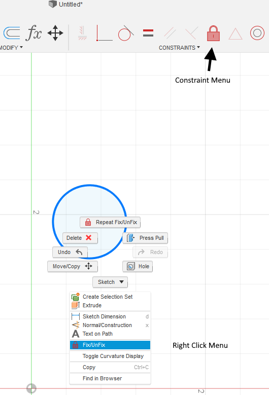
That origin point is important - but when I’m doing my initial designs, I many times avoid it so it doesn’t create constraints based on it before I’m ready for them.
The color of blue and black lines is significant. A black line means it’s constrained, the blue lines are not. So you can move the blue ones around. The black one wont move until you remove the constraint (it’s anchored to the origin).
Generally, you want all your lines to be constrained, but you don’t have to do this - it’s just good practice and becomes more important with complex drawings.
The D key will let you dimension a line’s length, but also allow you to dimension between to objects. So for example, if you wanted the top line to be 2" above the black bottom line, you’d hit d, click on the top line, then click on the bottom line and move the mouse out to the side and you’ll see the a dimension line pop up. You can enter 2" and it will move the blue line to 2". It won’t move the black line because it’s contrained…
Hope that makes sense…just a few tid-bits to help sketching along. It gets easier! Your post is looking good!
I have been getting used to fusion 360 but I have a few problems that I would like to fix before I can feel like I am really making so quality projects.
How can I eliminate the entry point from being left on good part of my project? There is a 1/16th-3/32 part of a hole on my part t
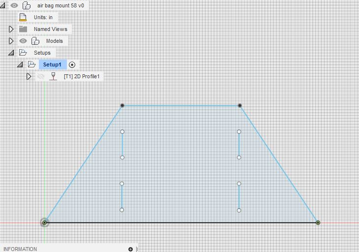
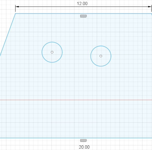
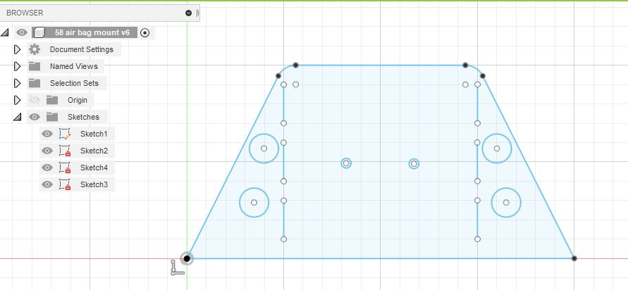
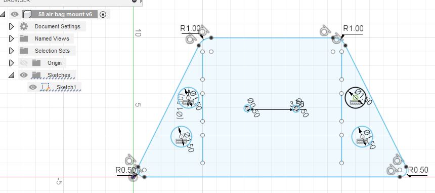
Referring to my “Air Bag Mount for the '58”. I added some mounting holes for the air bags, they are 1/2" x3 1/2 inches apart on center
A) I cant seem to center them with the middle of my plate… which is 20 inches overall at the base… so on center would be 10 inches… can someone give me some direction how to do this?
B) Secondly… you can tell some of my outer circles arent in the exact same plane as each other… can someone tell me the command or constraint so that they line up horizontally with each other?
Thank you James…see his tip below
C) Lastly… where might I go to learn nesting with the most efficient use of the overall plate dimension I would be cutting them out of… for example… the “welding gusset”
If I wanted to repeat this part and had a piece of plate whose dimensions are known… how can I get the machine to cut as many pieces as possible out of this plate at one time… is that going to be in fireshare?..or cad somewhere… I have "nest " turned on in F360… but maybe Im using the incorrect terms… I want to repeat the part I have generated to the extent it can cover a given sheet dimension that I might put on the table
Looks like full nesting capabilities might still be in beta form in f360 from a brief initial read
Outside cuts are clockwise red arrows
Inside are Counter clockwise red arrows
(Generally unless there is a specific reason… and Im too new to know what that might be… arrows direction can be changed by clicking on the red arrow toggling one way or the other)
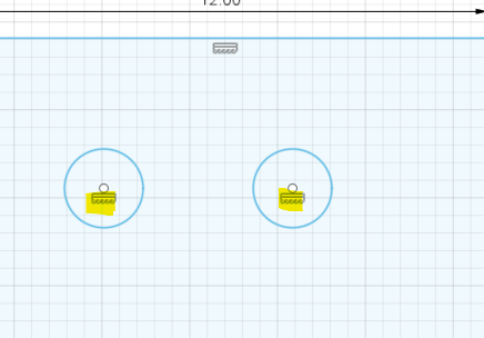
for your 2nd question: constraints can help you with that…
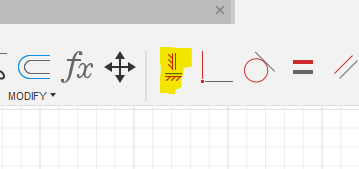
Click the Horizontal/Vertical Constraint, then click the two circles you are lining up. This will force them to be horizonal or vertical to eachother. Press the esc key to exit out of the constraint when done.
Notice the little symbol that added under the center point. That’s the constraint marker to tell you it’s contrained. Different contstraints have different markers. To remove the constraint, you can carefully select the symbol and hit delete.
Once constrained together, when you move one, the other will move within it’s constraint.
BTW, even though you added this constraint, notice the circles didn’t turn black. That’s because they are not “Fully” constrained. They can still move. Until you ‘anchor’ them to something else, they will be constrained to each other, but not the rest of the sketch.
Thank you james… excellent direction…easy peasey…worked the first time… faster than an elephant!!!
Tomorrow the last langmuir box arrives
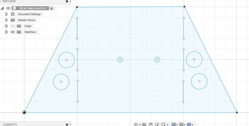
So…in reference to centering my mounting holes… using James tips on constraints I constrained the two mounting holes and moved them together to the center point I wanted…
Everything looks good… no red menace boxes. Also during setup I used the feed and speeds from everlast suggested feed rates …which was on another thread in this forum. It will remain to be seen how this will need to be tweaked. The feed rate was 46 ipm for 3/8" plate@50 amps/65 psi air.
Im still working on my last question about cutting multiples of the same part, in my case the “welding gusset” and nesting them to the size of the sheet I have on the table
There is a couple ways to do this in fusion probably more but this is the way I do it. First way i just highlight the whole sketch then right click and select move/copy and a popup will come up and at the bottom there is a check box that you can select that says create copy and if you check that box before you move it it creates the same sketch and leaves the original there.You can then continue doing that by selecting both to make 4 then 8 then 16 to whatever amount you want.
Another way to do is is to draw a line beside or above or below you sketch and use the mirror function. Same thing as the copy function select the whole sketch without selecting the line you just made and hit the mirror icon and a pop up will open up and it will show all the lines you have selected then under that there is a mirror line click on that and then select the line you just made and it will mirror your sketch on the other side of the line.
Mirror function also works well for you sketch above. If you had a line in the middle of your sketch and did those 3 circles and 3 lines on one side you could select them and use your centerline for the mirror line and it would do the exact same thing on the other side.
If you understand what I’m saying.
Another good way is to save your sketch as a dxf and using deepnest. When using that you can just open up your dxf in deepnest and select how many you want to make and add your sheetsize that you want to use or have and it will fit them in there up to the amount that will physically fit on the sheet size selected anyway. Deepnest - open source nesting software
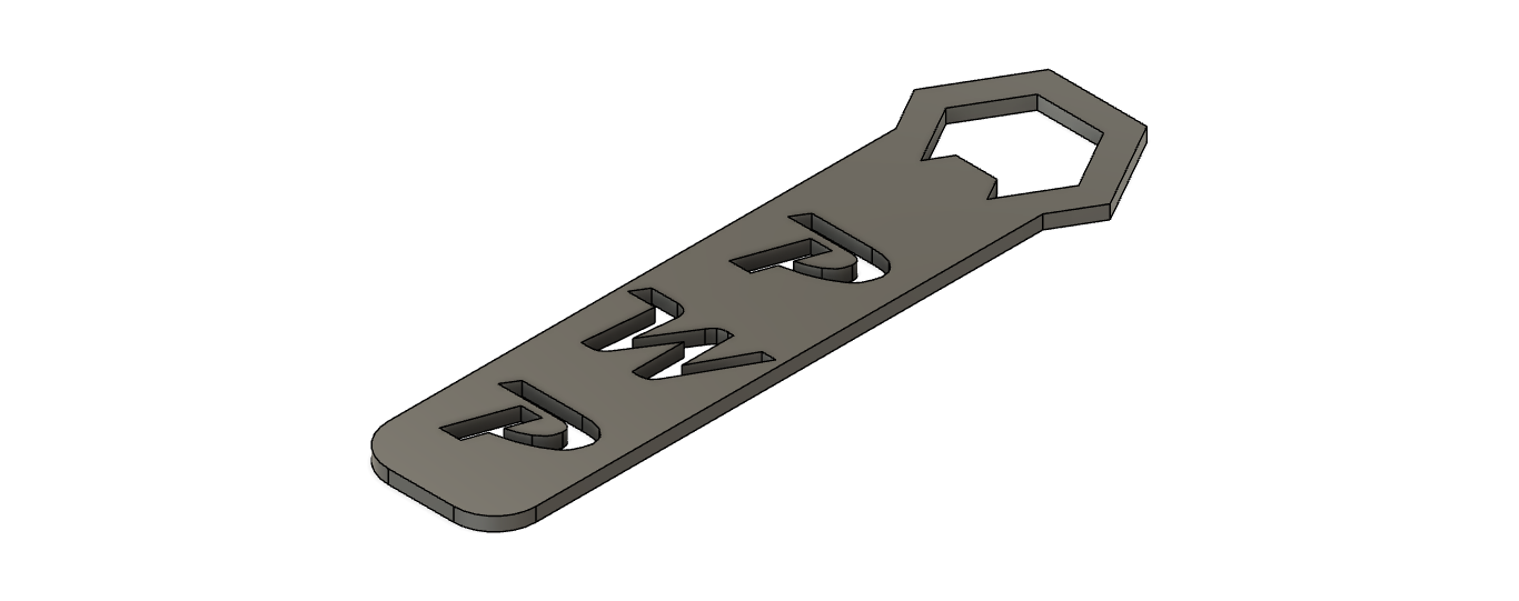
Well here is something I’m working on. Kinda like some of the others, while I’m waiting for my table, I’m trying to learn F360. My experience goes like this…
1- After watching several Youtube videos (several times) and shifting through the ones that actually slowed down and explained, not only what they were doing but also the buttons and mouse clicks they used. I felt like I could draw anything… Several attempts of drawing Desk, Razor Grills, Another desk, Desk top, Steel tubing and so on…
2- Reality kicked in and put me back in my place. I cant draw anything. (yet) I was trying to run before I could even crawl. I got aggravated, said several bad words and was considering looking for someone to do it for me.
3- Common sense kicked in. I need to crawl before I can stand and stand before I can walk and so on. So I went looking for a simple project to start out with, bottle opener. I didn’t really care about the F-Bomb ones and wanted to do my own. My company logo is based around the Tennessee Tri Star and a hexagon. So I based my bottle opener around the hexagon. (adding the stars is the next step)
4- Success!!! I finally did a drawing that I’m happy with.
5- Took it to CAM to try and get a tool path/ G code. After several attempts and clicking buttons and hoping it works… SUCESS!!! I have a tool path simulated and NO ERRORS !!!
Now I don’t have my machine to cut this on yet but I’m going to take to a friend who has a table and get him to burn it out. Fingers crossed it works for him.
Here is my first real / successful part drawn in F360
That’s great! Your part looks great! Take it slow! When I first dived it into F360, I got very frustrated as well. I wanted to build skyscrapers on my first day. Didn’t happen. Stepped back and took it step by step and things started to click. I’m still learning new things in F360 12 months later…so don’t give up - you can do it!
It will be a hit at the next office Christmas party in everyone’s sock
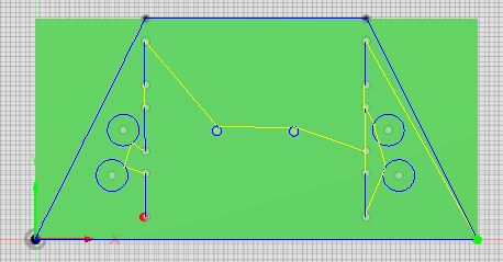
I continue to refine my air bag mount… added some radii
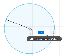
… I have a question about editing and resizing a hole in my air bag mount
I read the directions…push pull etc from F360 but that didnt work… Im trying to resize the top holes from 1.5 inches to 1 inch ( I know its operator error… FYI they are constrained to each other). I deleted everything except sketch 1 , which allowed me to edit it… the others wouldnt allow it because they seemed “locked”
That little red padlock before it says Sketch2, Sketch3, Sketch4 means the sketch is fully constrained. Just a visual helper to let you know whatever’s on that sketch has been defined. You can still change dimensions, though.
To change the size of that hole, just double click the dimension where it says 1.50 and it should open up a small window where you can re-type the dimension value. You can also single click it and move it around so it’s more readable. No need to extrude to change it.
The green means it’s ‘fixed’. I think you may have accidently done that. To un-fix it - you can use either the lock constraint or right click on the circle and choose fix/unfix (both do the same thing). Fixing an object locks it in place. You don’t need to do that here, but it’s sometimes useful.
You are invaluable Sir, thank you again… I am very appreciative… I would be lost with these simple questions otherwise. When I pose them in the Duck the stuff that comes back usually isn’t even in the same universe
I think if Im making these mistakes other new users will gain a lot from the tutelage being given
@notmeofficer
You’re right about others making the same mistakes… I’m in that category. It’s another reason I’m keeping my eyes on this thread so I can maybe figure it out in my situation.
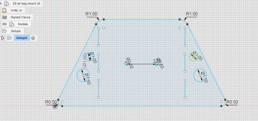
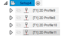
Well, I have just read through this entire thread (even the posts I added earlier in the thread) and I have to report back that I didn’t give up and have made a little progress. I do have a question as well, how do you make multiple tool paths on the same part? Like if you have a square say 4x4" and you have two 1" circles (holes) inside, how can you create a path for the perimeter of the square and one for the two holes? I’m sure it’s easy but I would like to hear from the pros instead. Thanks in advance.
I would tackle your part with 2 profiles in 1 setup in Fusion.
I like to do all my work from the middle out. So Holes first, then cuttouts, then perimeter.
In fusion you can generate the gcode for all profiles in a setup by selecting the setup and right clicking on it. Select post process in the drop down.
In the picture here the Setup is Setup4. It has 4 profiles. you can move the profiles up in down in order (this is where I set inside to outside order).
Each Profile is created the same as you would for any part.