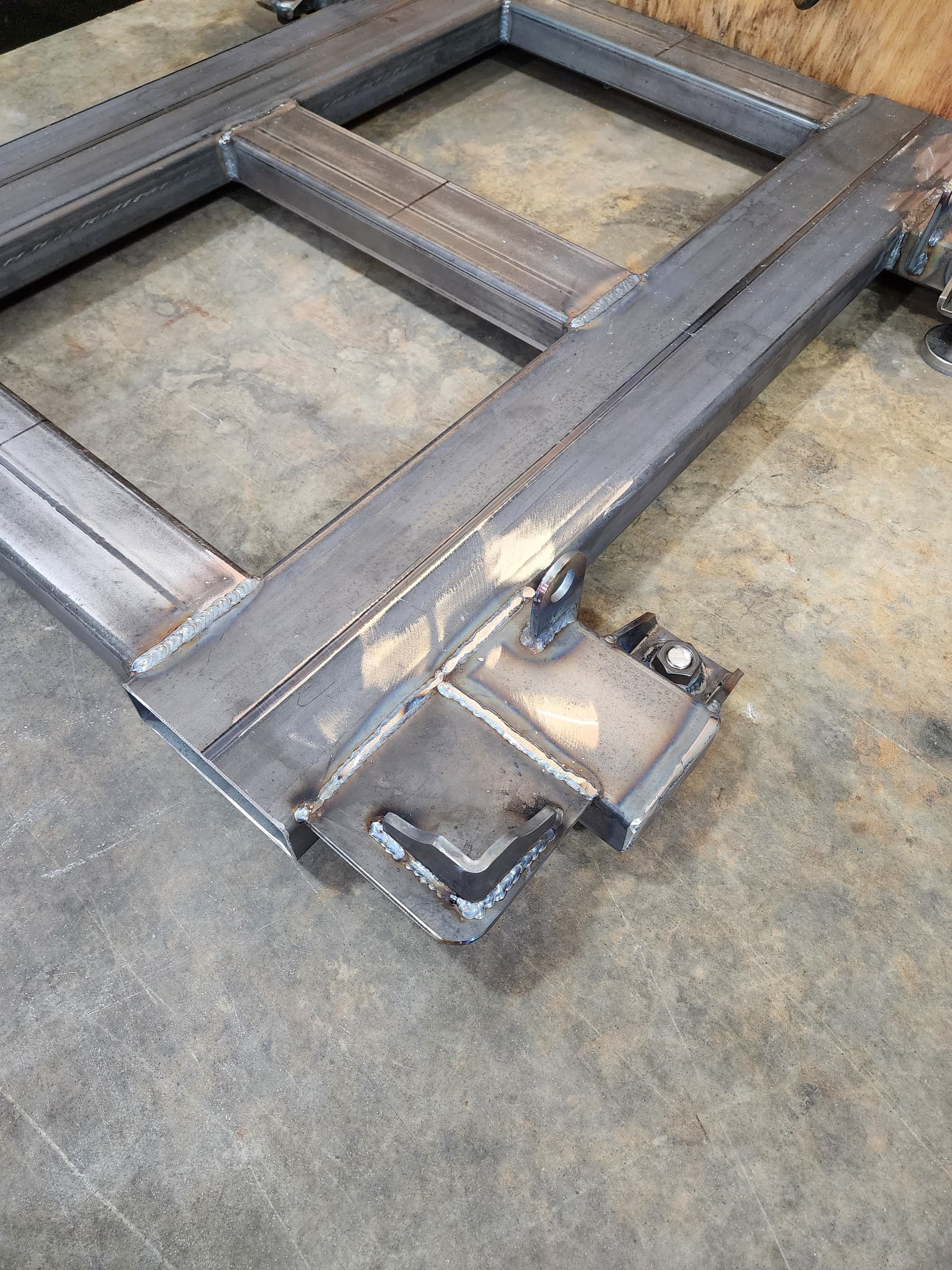
Built the support skid today to be able to move my MR1 around the shop if necessary.
Still needs 11 ga plate on the top to support the coolant tank. I’m waiting with a lot of patience.


10 Likes
Nice. We don’t have a forklift. I was thinking about drilling holes through the sides of the legs, about 4-1/2" above the ground. Then I could slide 3/4" pipes through the holes and move it with a pallet jack. Then I could remove the pipes to clear the space under the front of the machine. I’m sorry, but whenever I see those legs I have to think about the old Craftsman table I saw I used to have.
2 Likes
I plan to bolt the mill down to the skid prior to me pouring the concrete. I believe I’m all ready to go. Been tripping over 10 bags of cement for a month now.
All my wiring is completed and the emergency trip relay is installed on the spindle power circuit. Even got two explosion proof light for the inside of the cabinet.
It would be a good idea to design the bolt down such that you can adjust it if you ever move the machine. With four points of contact, the whole assembly will tend to twist a bit if the new surface it is moved to is not identical to the original. You would have to reface the bed after every move, and you may run out of bed to surface. If you make it adjustable, you can move the spindle with a test indicator around the surface and return the bed to flat and parallel to the x-y plane of the machine.
My plan was the skid is my level adjustment.
It has 4- 3/4 -10 threaded leveling feet. The skid is very Rigid. I’m hopeful that I won’t have any problems. The concrete will be poured and setup while the machine is bolted down. Well thats the plan anyway.
I too would like to be able to move the unit - how about a more rigid base? I have some 4” I-beams and heavy tubing which I can weld into a supporting frame. I guess the challenge is not having the frame twist at all with a 800 lb load on it which is not easy for a lighter planar structure… the machine weight would be distributed across the corner points which means a suspended corner (ie crossing a dip in the floor) would need to support 200lbs or so with practically zero deflection. Hmmm, need some stress-strain analysis done …
1 Like
This one won’t flex with the 900 lbs mill on it.
I don’t plan on moving it all over the shop. Just want the option to move it without damaging it.
2x6 and 2x4 - 11ga tube with .250 steel top.
I was going to use 11ga for the top plate but had the same concern you had. It was the first time I had ever sprayed bedliner. I have little black spec all over my head. Tough crap to get off…
1 Like
Even with the tubes oriented in the weak direction, I doubt it will deflect much simply because the moment arms are so short between your leg supports and your leveling feet and between your forklift tubes and your leg supports.
If I get a min maybe I’ll do a quick FEA(finite element analysis) on it… you have me curious.
Getting the tube to mesh with the plate will take the longest but it shouldn’t take to long.
2 Likes
That would be wonderfull. The thing weights 200 lbs and super rigid. Don’t believe it will flex with 900LBS on it. I will sleep at night if I knew.
Send me the dimensions… or a good un-skewed overhead shot with at least on dim. I could use the tube width, but better input = better analysis
42" x 45" wide. Foot print of MR1 is 38" front x 39" to rear. 2X6 11ga tube for forks and 3 2 x4 11g cross beams. 1/4 " flat plate welded to top.

onto the top.


4 Likes
That top plate should really help. It will almost turn it into a torsion box. Another thin plate on the bottom would help.
Waiting to see the finite element analysis that 72pony is working on. The thing is pretty stout. If I need too I will.
We shall see. My small forklift forks will only go 39". Thats why I did it like that.
1 Like
I haven’t forgotten about you. I made a couple tweaks today. I have a big report due today so I have been super busy. Should be able to get a min to finish this off tomorrow at lunch.
1 Like
No problem. I really appreciate the effort.
RESULTS:
John,
When mounted on the fork truck with a 1.6 factor (for impact) the maximum deflection for your skid is 0.009 inches. I would say that is pretty darn stiff. Without considering the 1.6 factor the deflection would be 0.006 inches
I still need to check the at rest condition sitting on the feet but I think its pretty safe to say your skid is quite stiff. I have some output I will send you with the stress contours if you would like to see them. I will try to get to the at rest condition either tonight or tomorrow at lunch.
Been a fun exercise for me… thanks for playing along!
Also I really enjoy your contributions to the forum!
Erik
Special thanks to 72pony for running the FEA (finite element analysis)
Freaking NASA stuff…
2 Likes
I think the machine builder should add cross bars to the legs so it could be lifted with a pallet jack.
1 Like
Nice job, Just what I need how much $ do you want for it?
After I get my machine hopefully in a couple of weeks and get it bolted down I will let you know.
Problem is it weights so much it would costs a fortune to ship.
I’ll be glad to send you a drawing and parts list then.
1 Like
This is a great idea @Bigdaddy2166, I’m going to look into doing the same. Question on the design. It looks like the actual machine sits on flat plate, that extends off the rectangular tubing. Why not use the rect tubing (that extends out to hold the leveling feet) as your base for the machine to sit on? Moving those tubes to be directly under the machine would also widen the stance front to back.
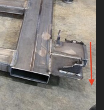
Yes, I would do that if I built it all over. Started the project and found out my small lift truck forks only went to 39 ". The 2x4 leg support is not wide enough for the machine leg footprint.
3 Likes