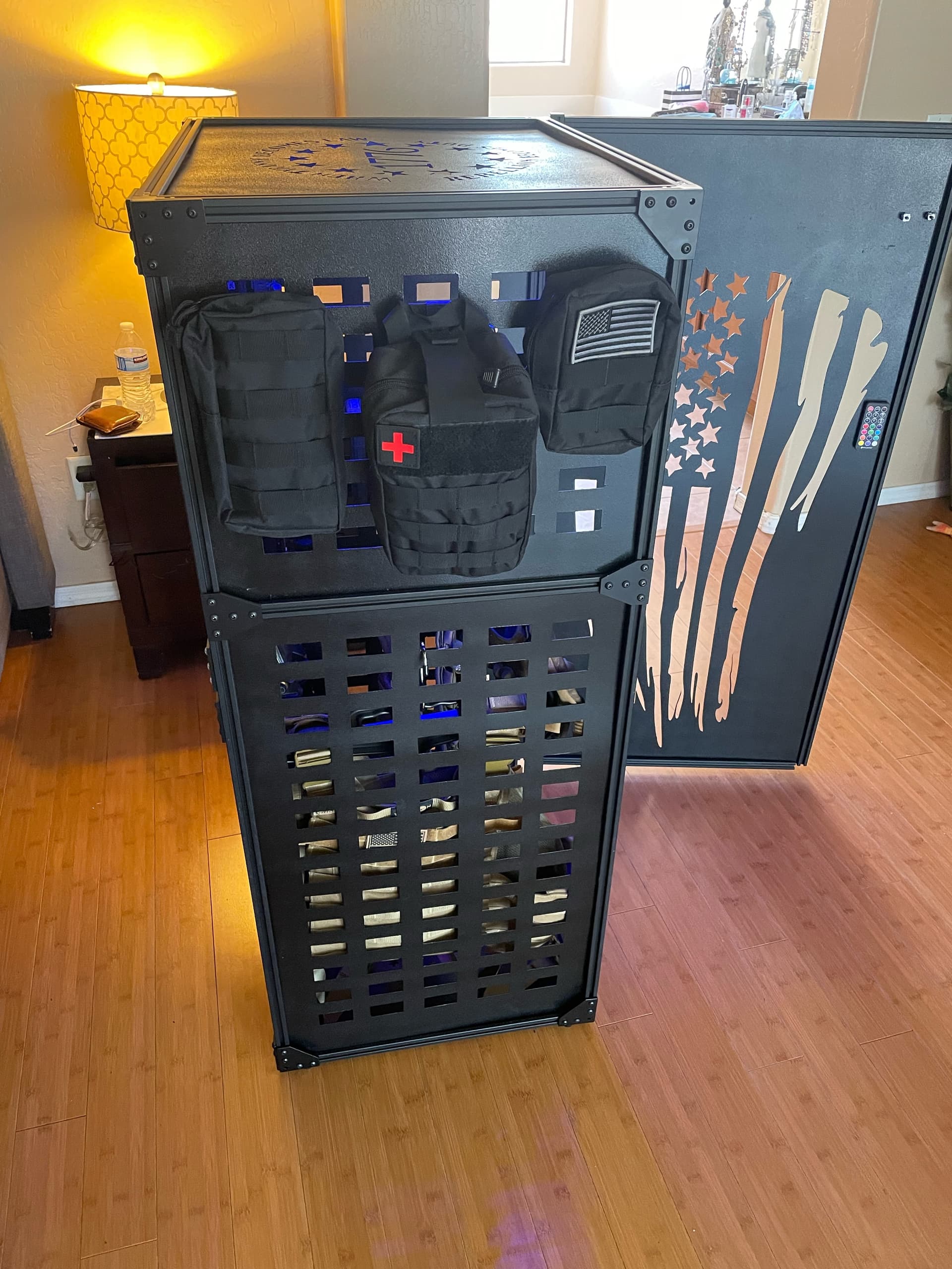
I figured out a bunch of other issues I still have to fix like thc firmware upgrade, it likes to travel to high on some of the returns. I need to open the razor and change the psi at the cutter.
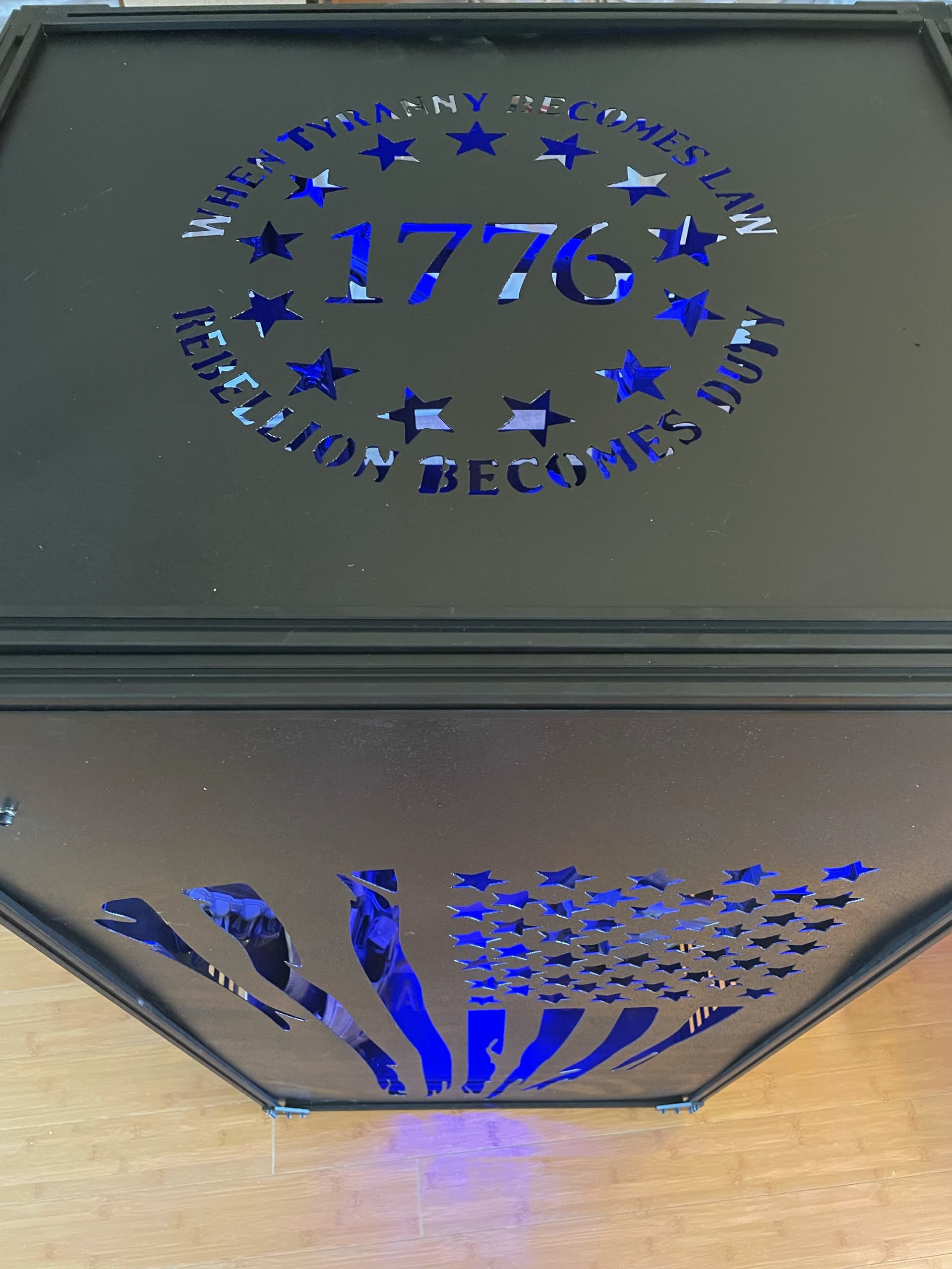
Why not add a little radius to the molle holes, like 1/8 inch or so? That will prevent the slight over it for sure. Also watch for deflection of the workpiece. Those tiny imperfections aren’t always in the settings or tool path.
If this is a file you’re going to be cutting a lot and you want it perfect, it would benefit you to manually designate start points and lead out types.
Most of my work are one offs, and I just leave my sheet cam toolset at 1/8 inch arc lead in and out. I rarely end up with dents.
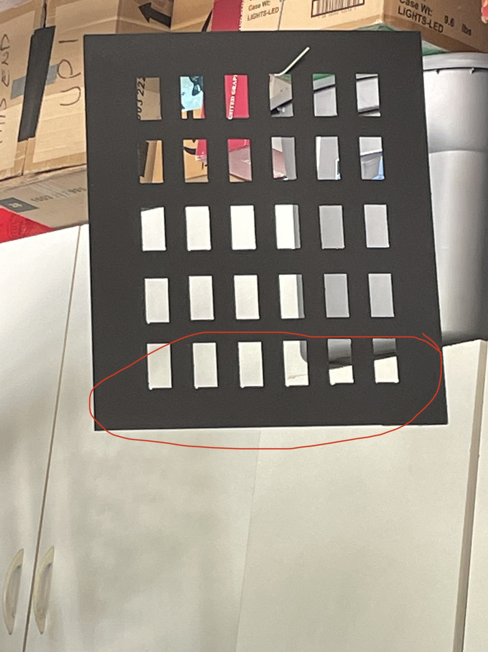
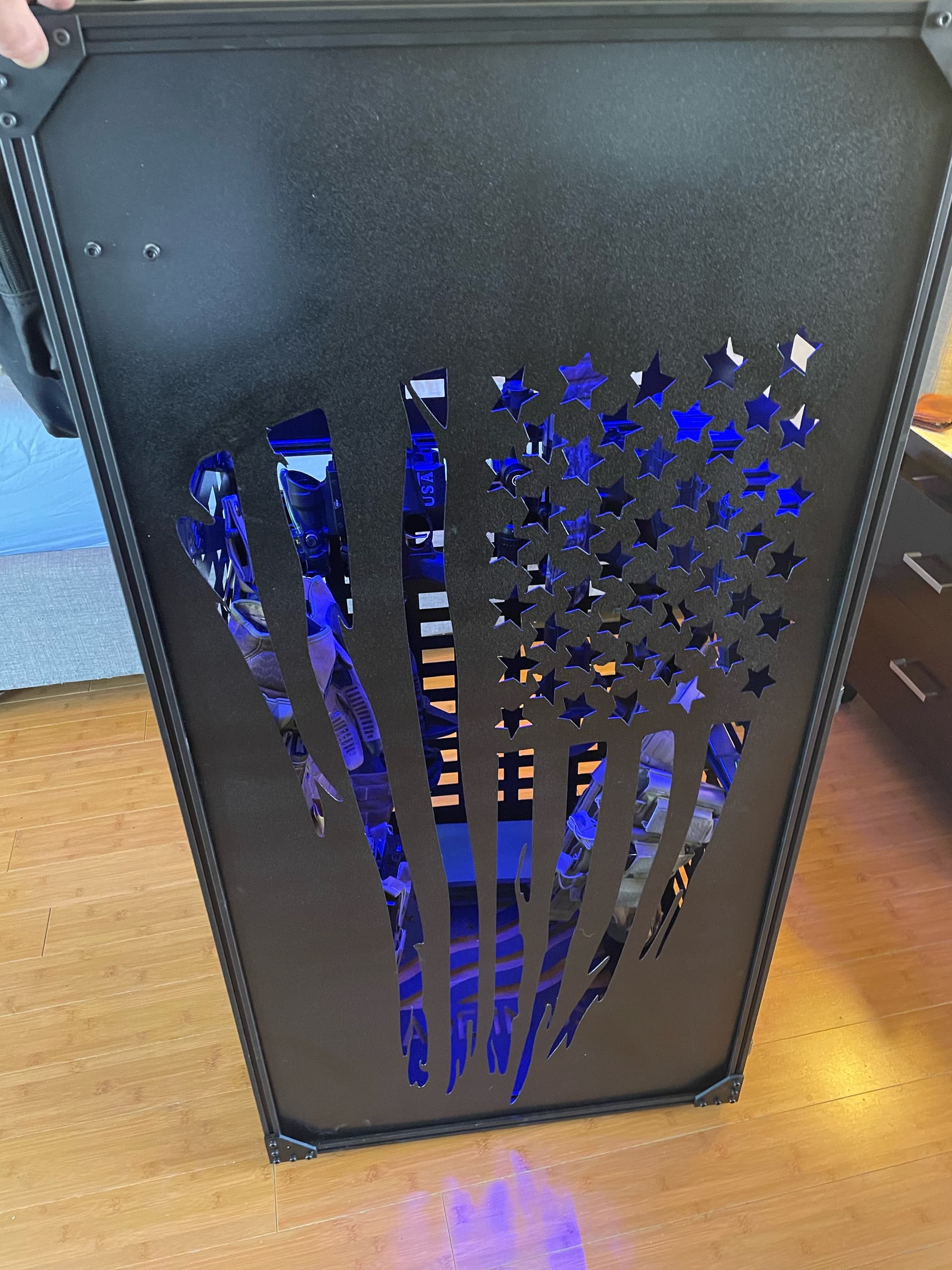
Watch which side of the line the toolpath is on with those letters. That surely looks like the 2 “T”'s and part of one “B” was cut with an outside offset, which is why they are larger than the rest of the letters.
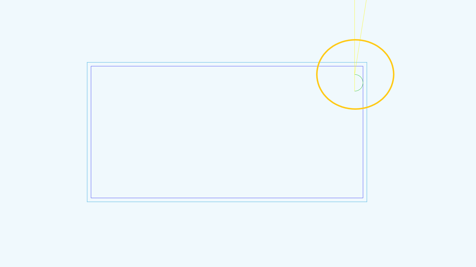
A lot of times when people think the divots are from the lead in, they are actually from the torch shutting off at the end of the cut. A lead out will help with that issue.
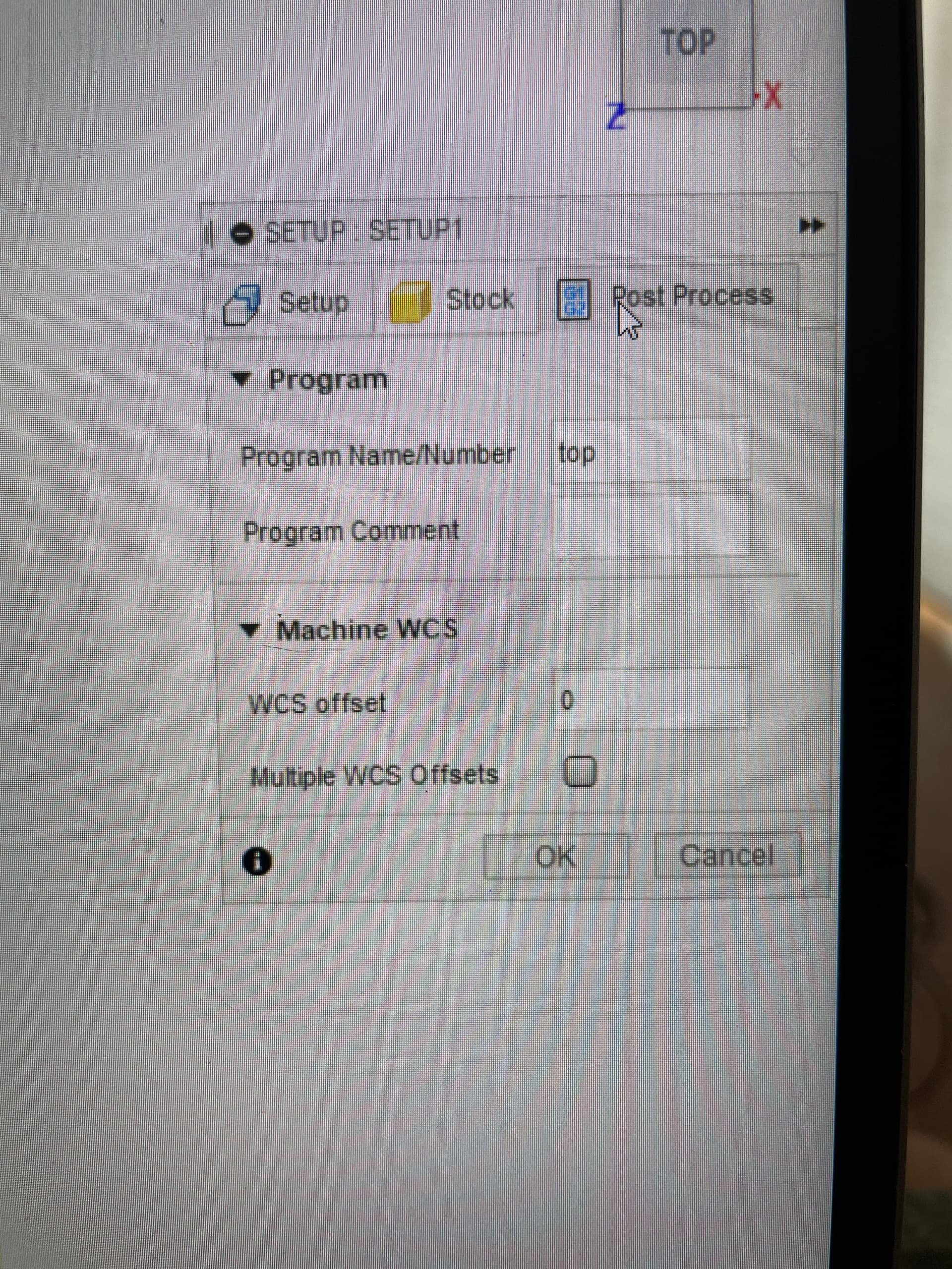
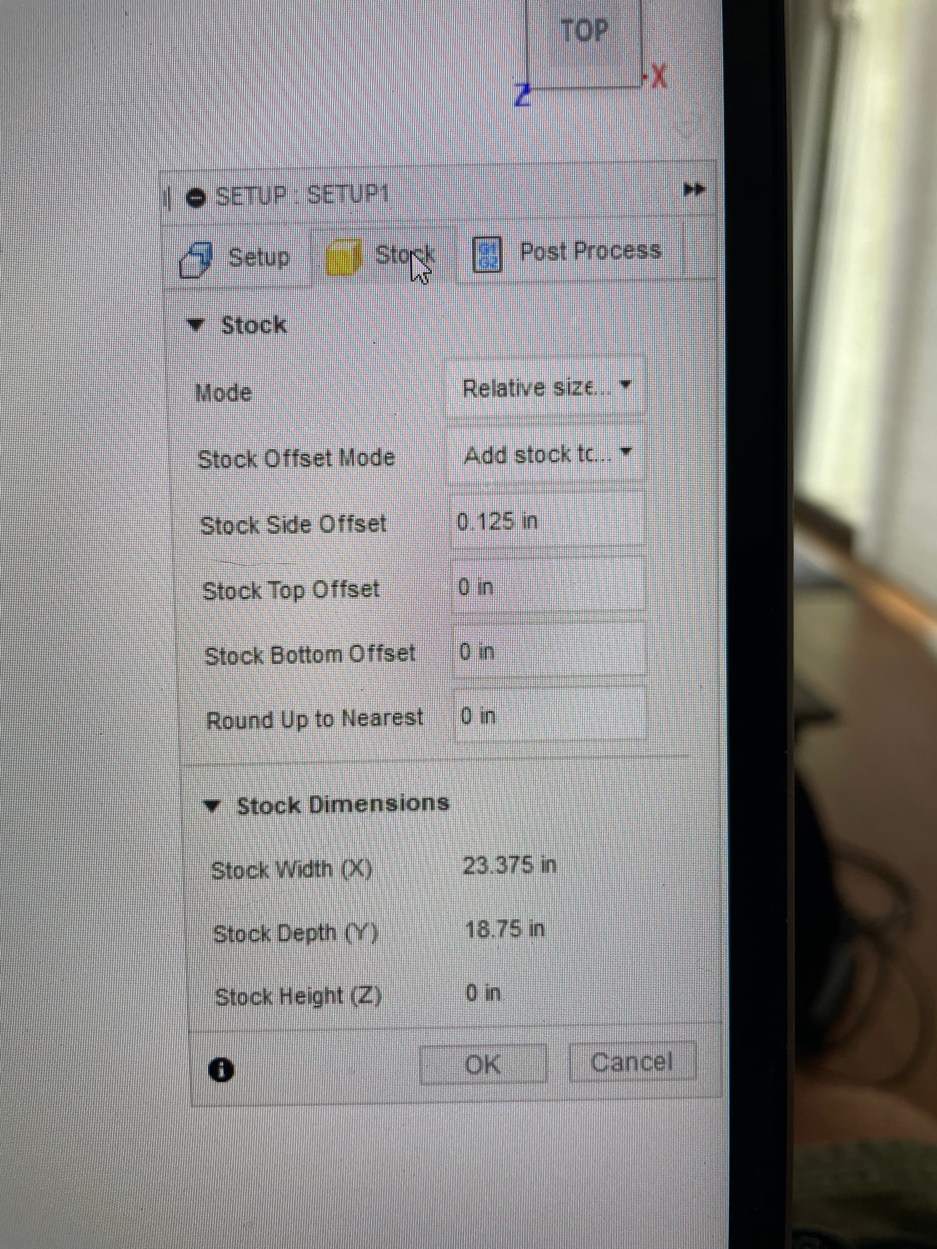
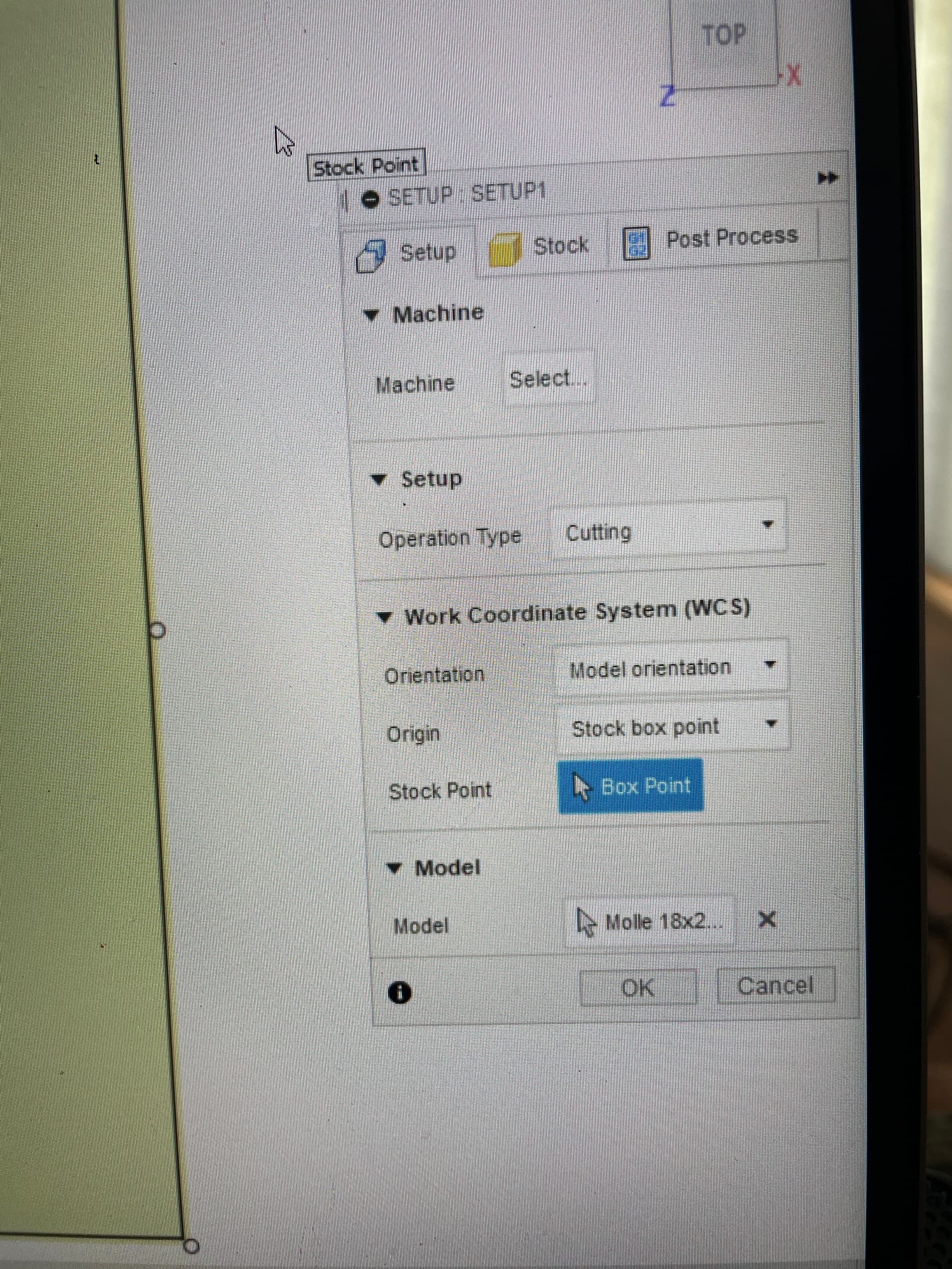
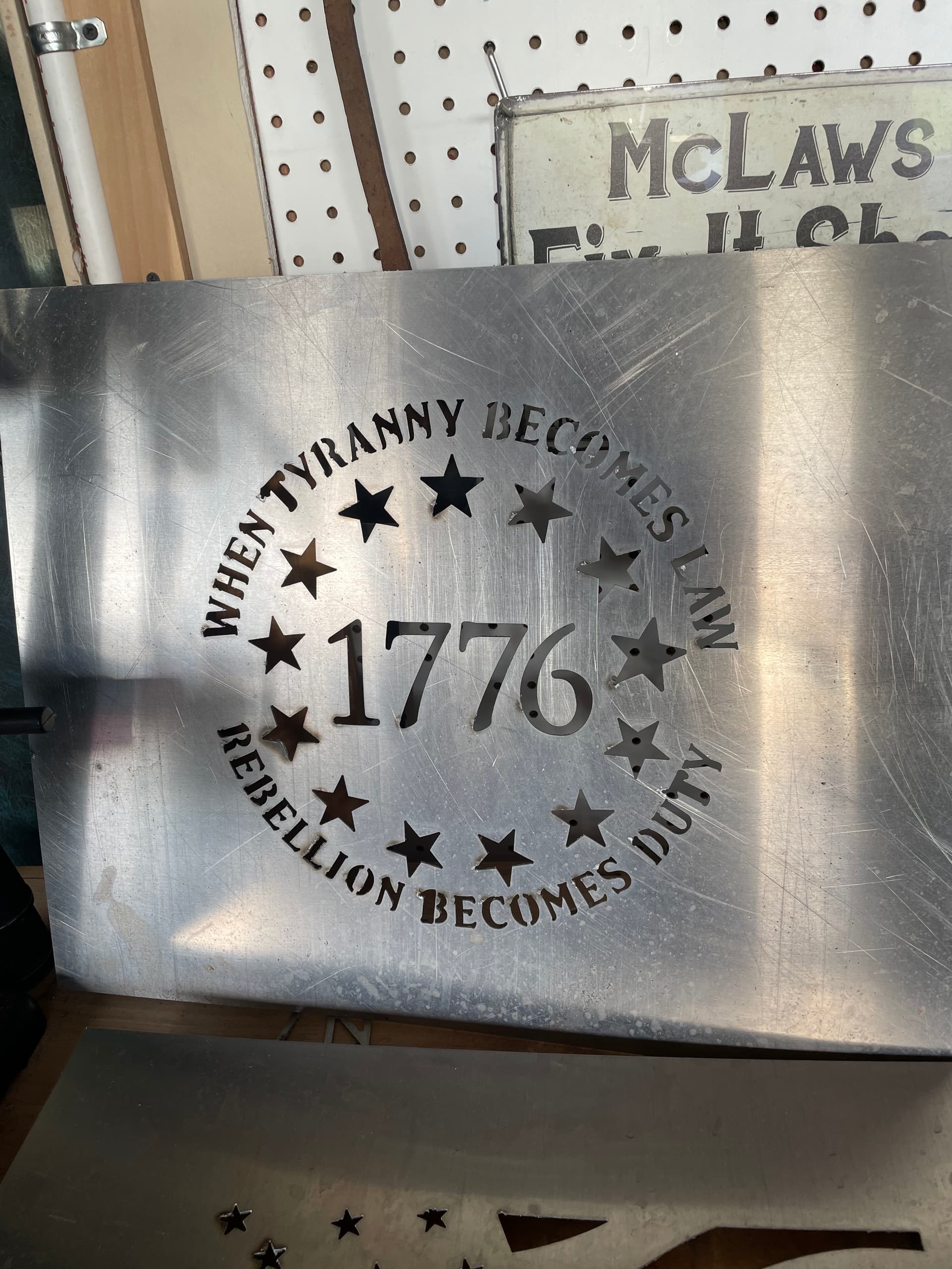
Did you make the CAM for the 1776 panel with F360? I do not see any manufacturing data in the F3D file.
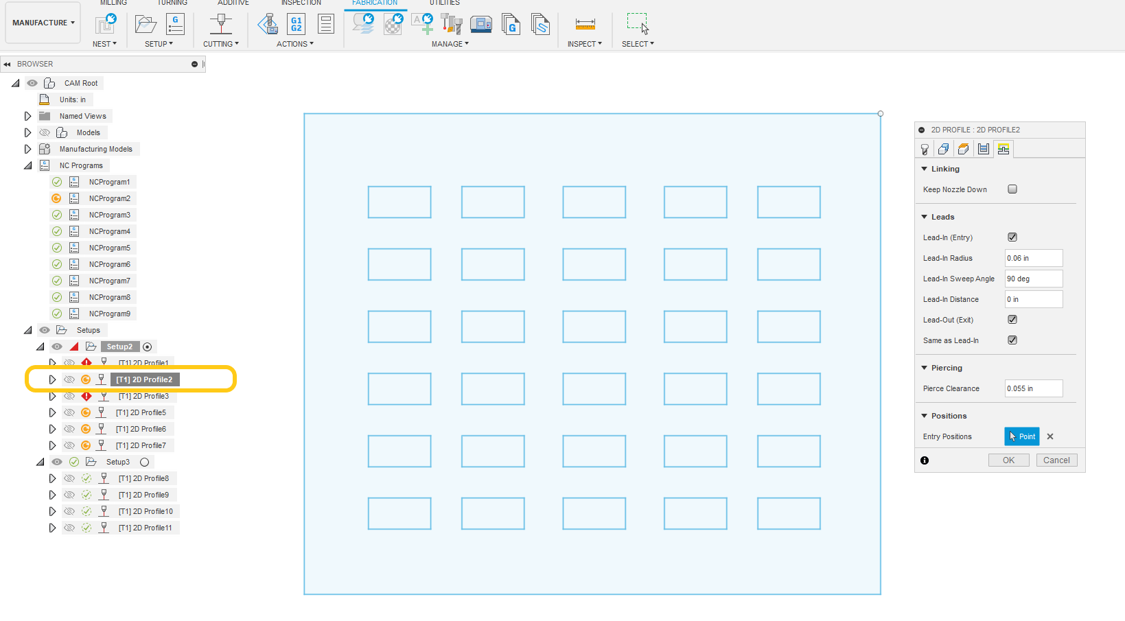
As for the Small molle panel pictured above the manufacturing data was included.
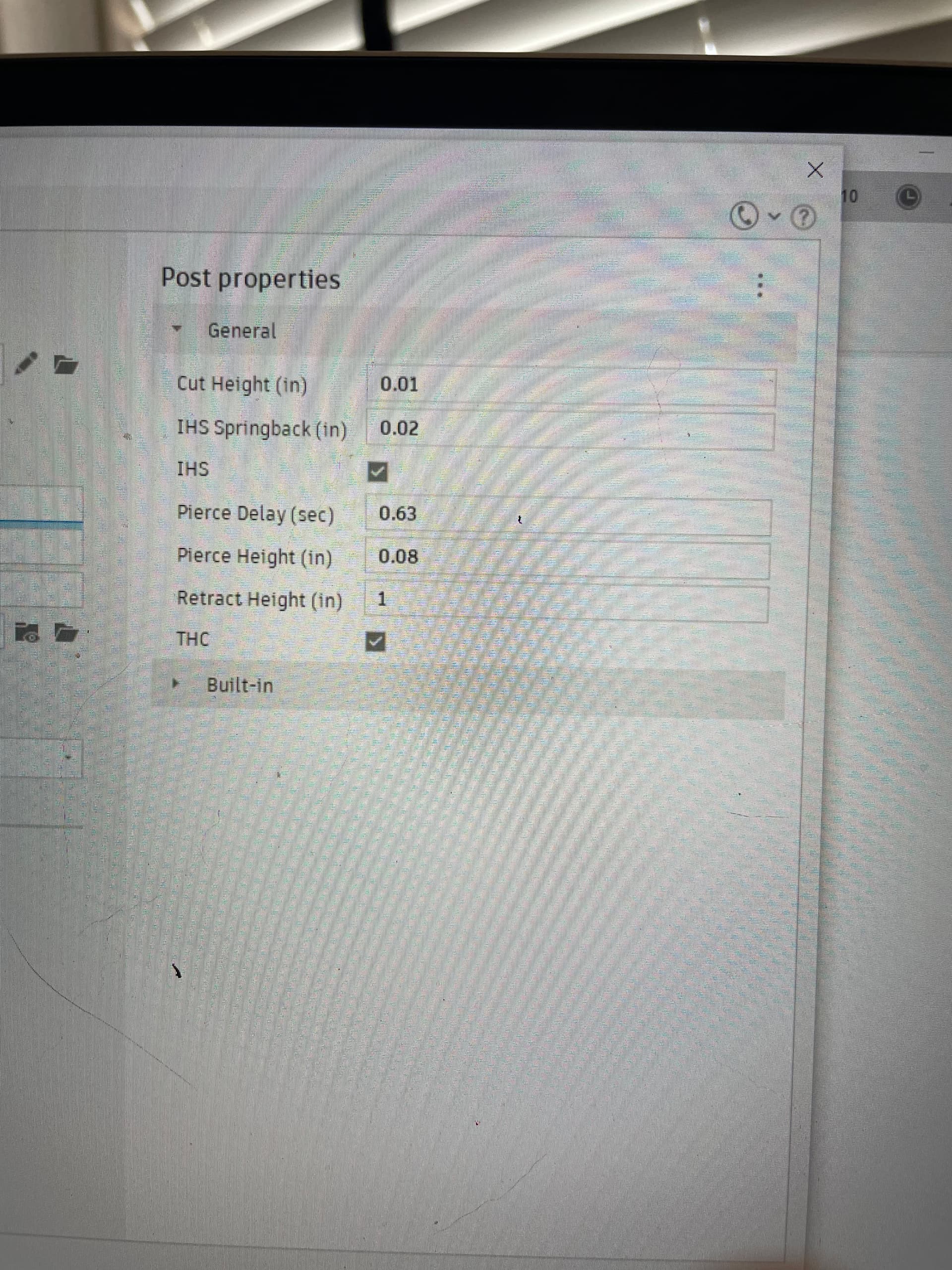
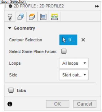
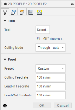
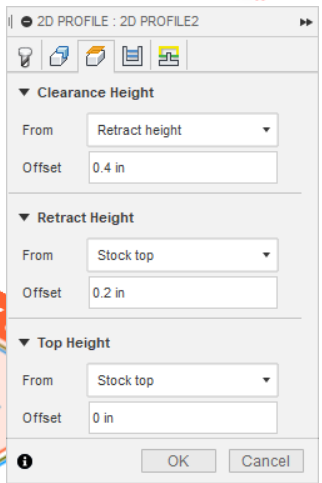
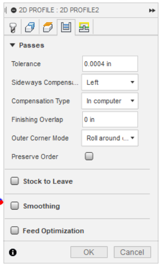
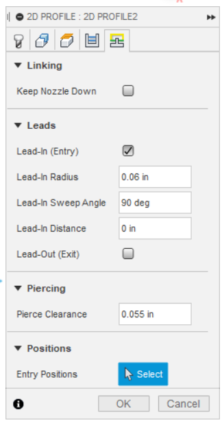
The screen above was not the parameters shown in the file . here is a screenshot of the information of Profile2 . I feel that your lead in and out is very small and close to the next 90 deg corner so its cutting in.
Another tip. Try to extrude the sketch geometry into a body before moving into the manufacturing workspace. This will vastly simplify the toolpath selection process and eliminate the “which side is the arrow on?” issue.