Hi, I was hoping to get some help troubleshooting my cuts. If anyone could help me dial in my settings for this 1/8" mild steel, it would be a huge help to me. These are some photos of my third cut for this little test sign. I am hoping to make something similar, but bigger in the coming days and I want to get my act together before I got wasting a big piece of steel.
Extra Info: I bought this table over the summer at an auction online. Someone beat the crap out of it, and I’ve (very) slowly been fixing it up. I’m just getting started with plasma cutting in general.
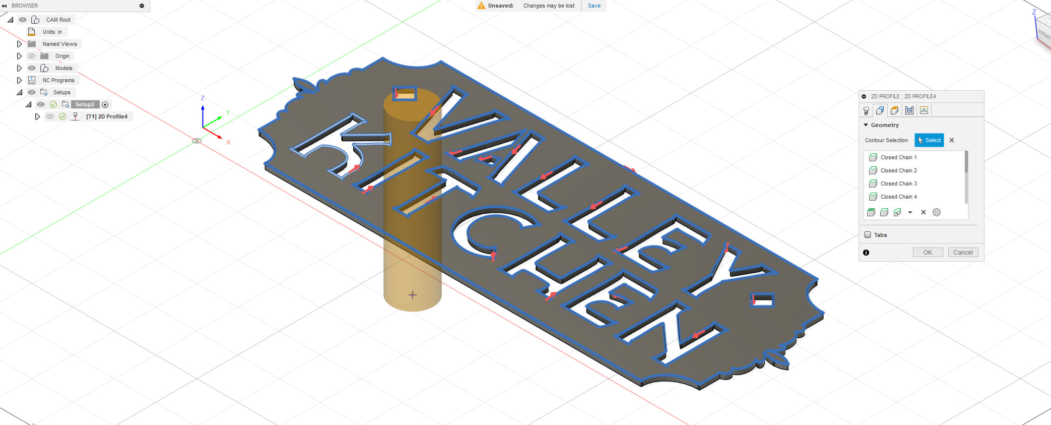
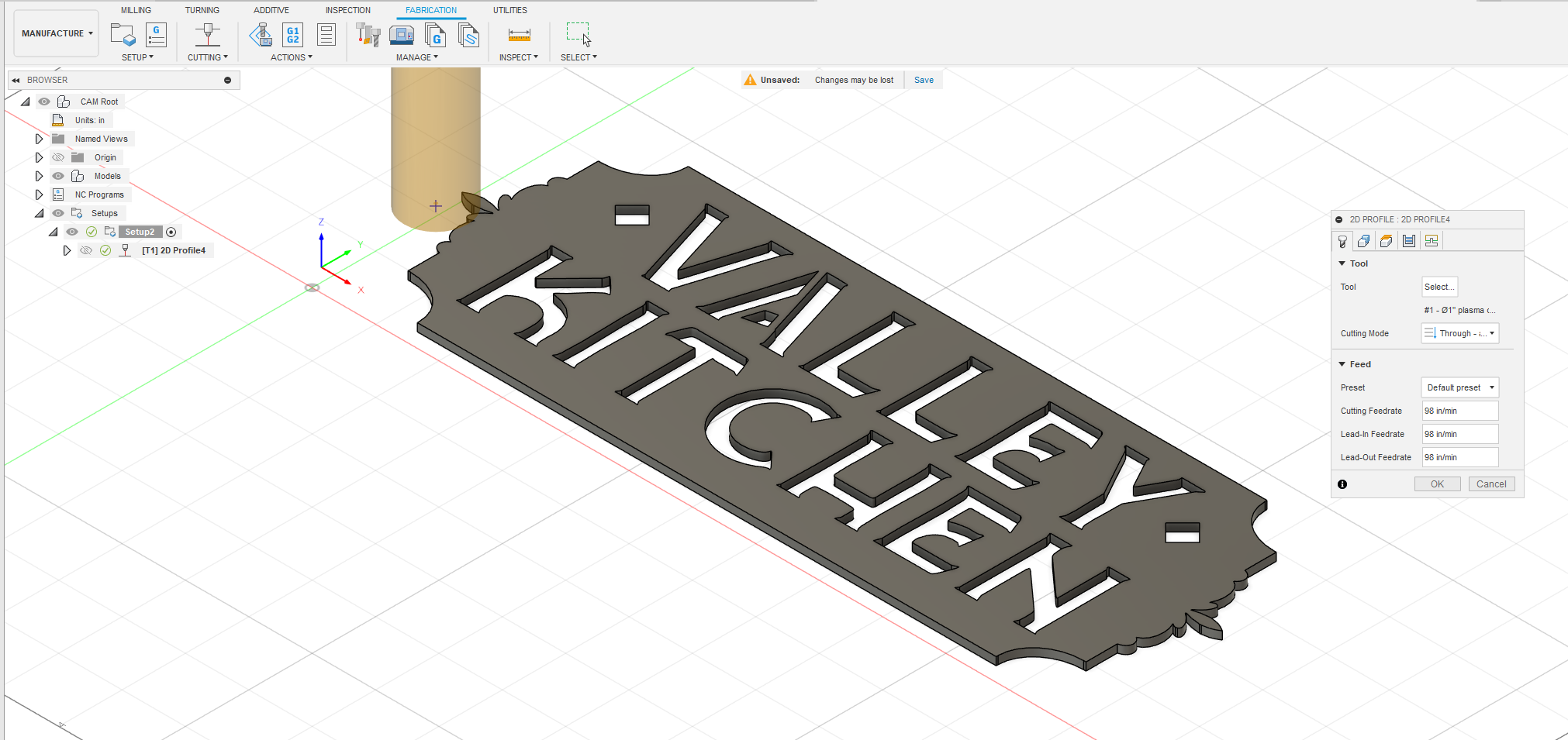
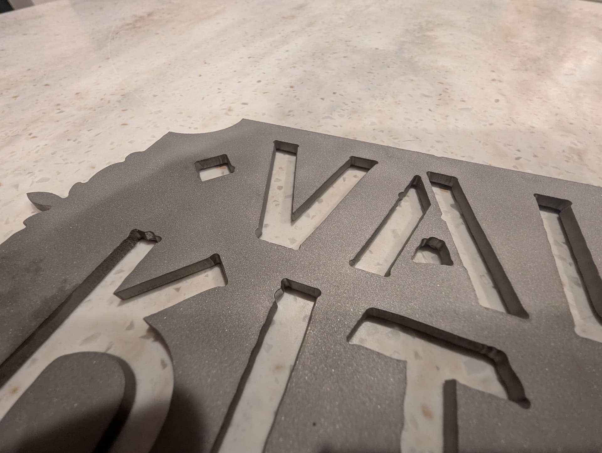
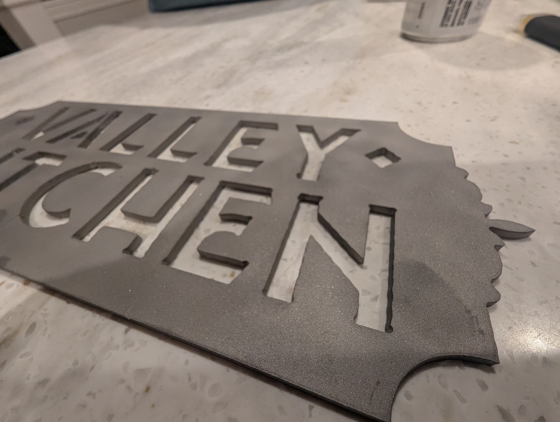
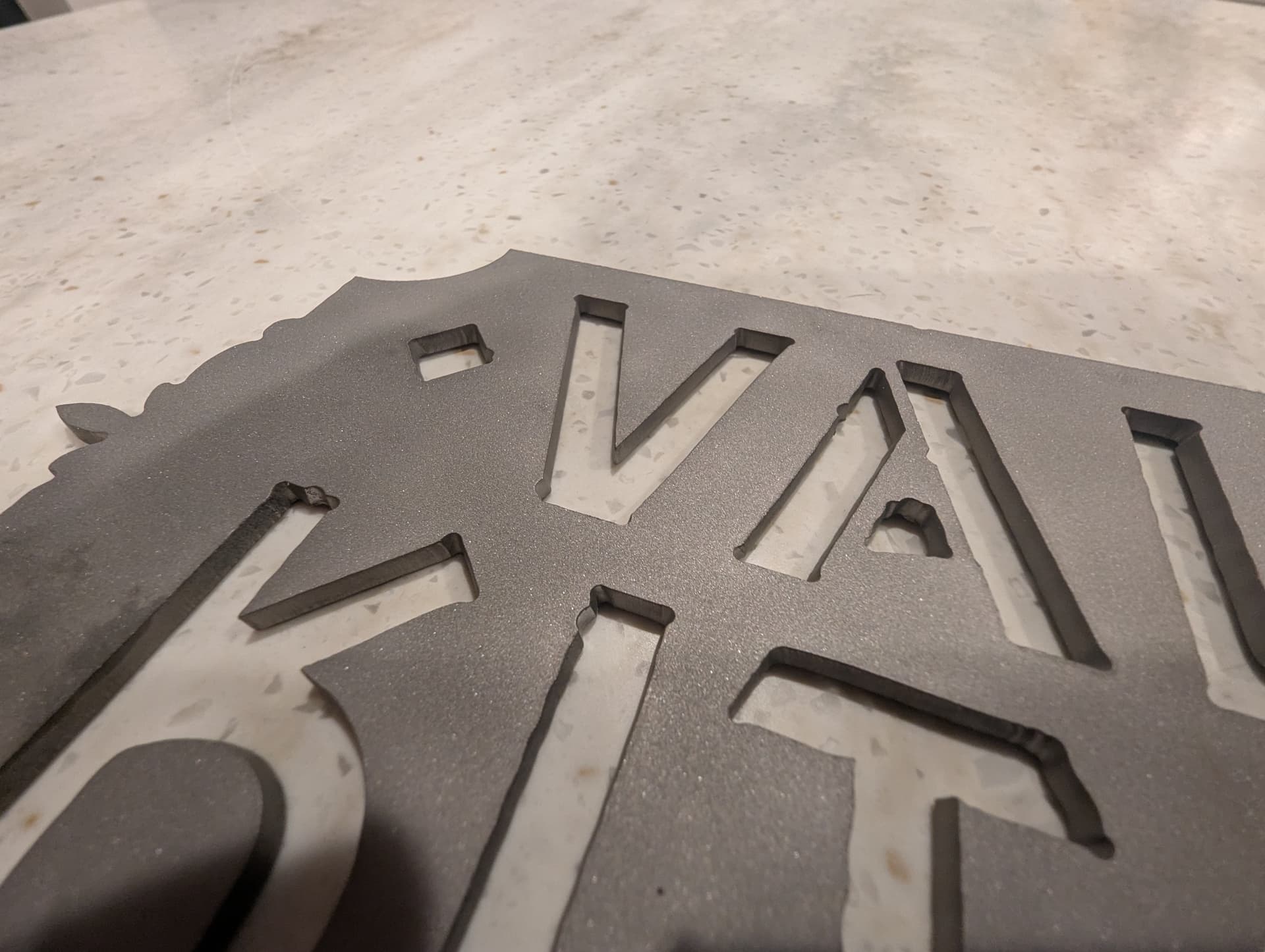
This is a quick little test sign I did in Illustrator and imported to Fusion 360 as a DXF. I’m attaching some photos of my Fusion 360 settings and my workpiece for reference. There’s a lot of what I’m thinking you’d call “pierce” marks? Also, there’s some “wiggling”. I am struggling to understand what’s going on here. The wiggle seems to be in the vertical letters, but not so much in angled cuts or horizontal cuts. Maybe that’s just me? I would really love some advice on tightening this up or places to look for the root cause of the wiggle. Like I said, any advice is greatly appreciated. I’ve also spelled out my setup in more detail in my profile if that helps. In short though, I am using the Pro w/ machine torch, Razor Cut 45 (set to 40A, 73PSI), THC.
Thanks so much to anyone who has a minute to help me get started!
Hi guys! I’m sorry if I’m violating the forum rules, but I was hoping I might get some timely feedback to help me through this project. This is my 3rd cut, and I was looking for some advice on reducing the pierce marks and waviness in some of the lettering. I am using the Crossfire Pro w/THC, Razor Cut 45, my air is coming from a 7.5hp 80gal IR compressor with RTI filters, mini desiccant dryer and a motor guard just ahead of the cutter. This steel is 1/8". My goal is to make a 3’ one that would look similar for a new restaurant that’s in construction, so any advice on how to clean this up would be really really really appreciated over here.
If you wanted the wiggle, it is sort of a cool effect but I can understand wanting it solved.
I would go thru each bearing block and readjust as per the assembly instructions. This could be caused by something like the bearings being too loose, torch having some slop, worn out bearings, lead nut has excessive wear or the connections of the lead screws to the motors are slipping.
Thank you! Yes, I believe it ran a little during this one, but I can’t say how much. That’s an interesting thought. I have it anchored to the concrete floor on some rubber pads.
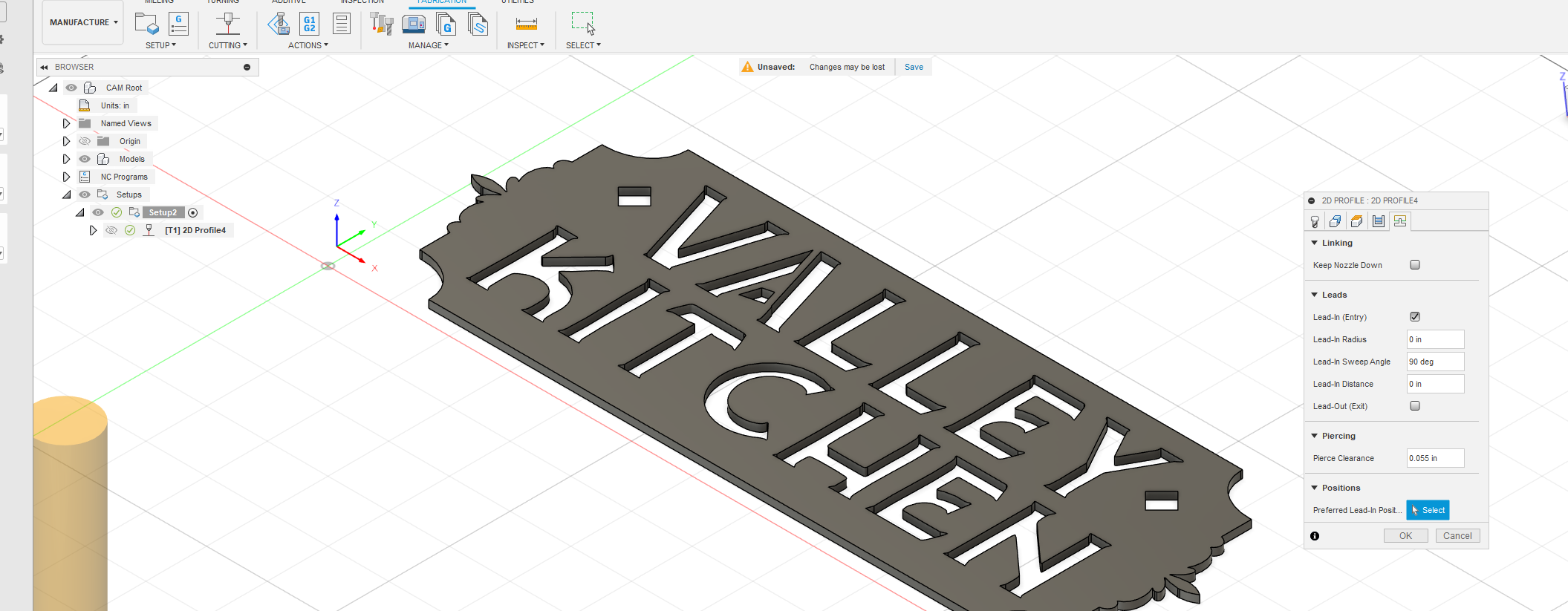
Thank you. I was basically following the videos page for settings, and I thought I recalled the narrator making a comment about setting the lead-in value to zero because choosing the
“computer compensation” type, that would handle the lead-in value. Are you able to clear that up for me? I was under the impression I was letting that be optimized for me. Which sounds great to someone who doesn’t know what they’re doing.
Thank you. It was really rode hard and put away wet. Or dry… Or both.
I bought some bearing blocks from Langmuir and did the worst looking ones, and with the old ones I am punching out the pins and replacing the bearings and washers with skateboard bearings. I still have a few more to do, but most of them are new. I’m trying to get them all done, but I’m also practicing in general.
I will go over these parts of the machine and make sure they look/feel good to me. Thank you for the link too.
Generally, you will want a lead-in of some type unless you have picked “center compensation.” Center compensation is a unique thing when you are using single line cuts as opposed to loops/contours. There was a guy here that cut everything with center compensation and I would not be surprised that you heard “no lead-in”.
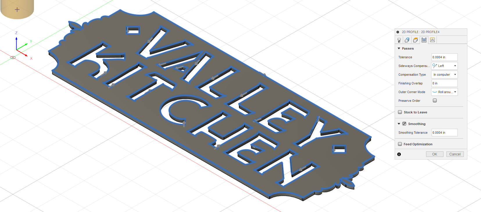
If you are doing anything that needs to be dimensionally correct you will generally pick “left compensation.” That will put the torch on the left side of the line according to the travel of the torch. The right side of the torch will generally make the better cut (less bevel).
Thank you very much for this explanation. Can you do me another quick solid and check this 7:38 timecode on this video and make sure I’m not just making things up? I took this as, “Go ahead and delete that lead-in value, because the computer is going to work it out for you, Fred.” It also winked at me. I swear…
on the lead in, he set the lead in radius to .06 you had 0. Go ahead and play with different settings on the lead in and then go back and see what it looks like when you generate a cut path or run the simulation.
Just for the heck of it grab the torch mount and see if there is any play in it in both directions.
Also check and see if the there is any play in the gantry. do a search for couplers slipping and check those too.
Yes…exactly as Knick explained. That video has aged a bit. And nearly everyone sets the pierce clearance to 0.0. It is not needed.
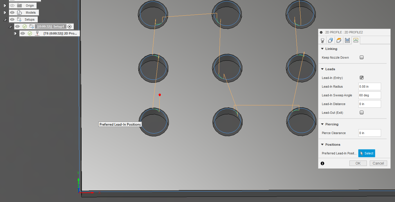
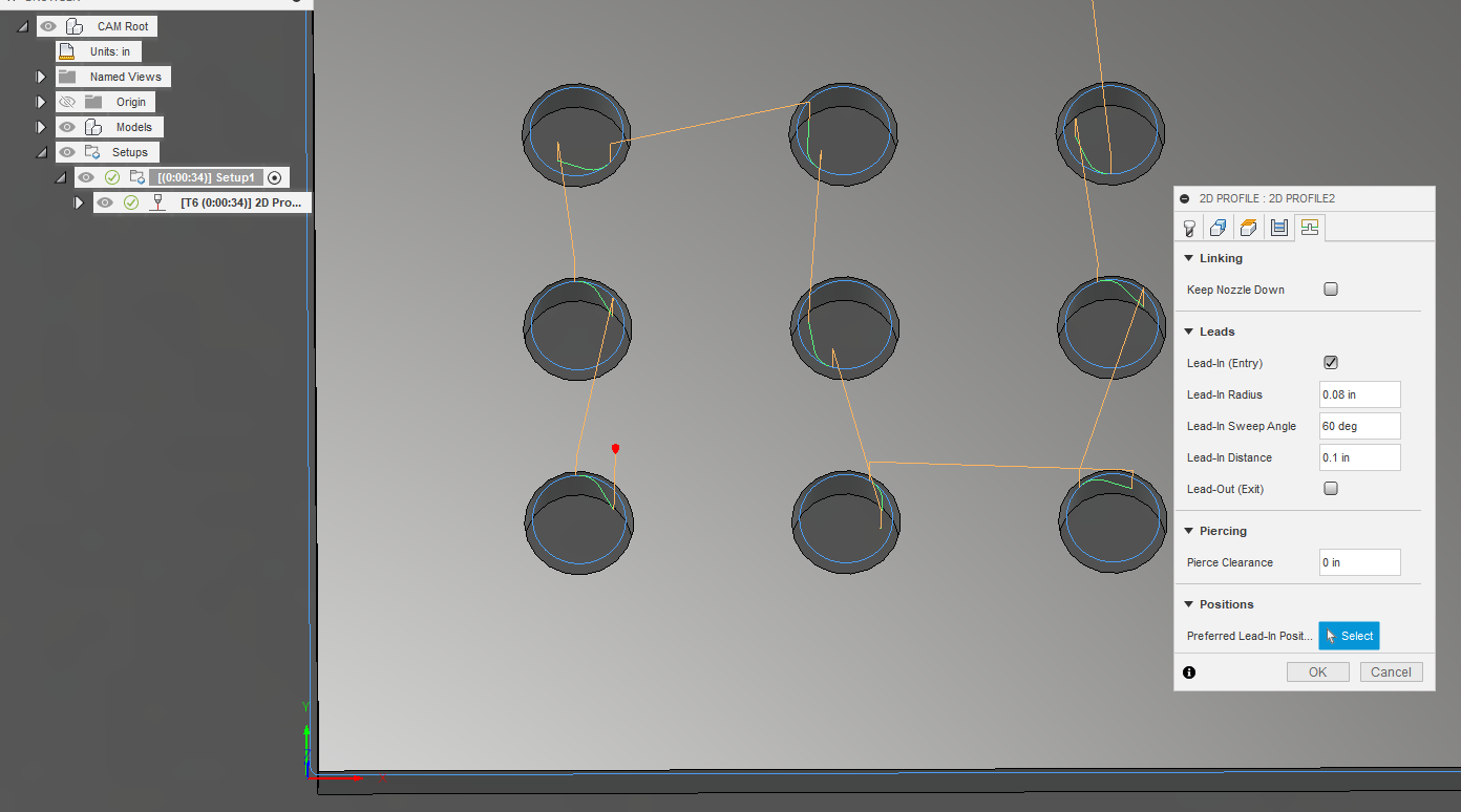
There is multiple ways to get a lead-in and it seems there are all sorts of opinions and tried and true methods but let just look at the lead-in radius and lead-in distance of a 3/8" hole:
First is a 60 degree sweep angle with a lead-in radius of 0.08 with no lead in distance nor pierce clearance (no pierce clearance in any of these examples)
This is a really good, concise summary for lead-ins from Tin. You will find that he does lots of testing before he actually shares his results so his advice is very good:
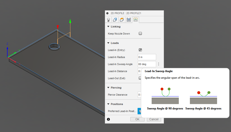
That is interesting that Fusion treats the lead in distance and radius as two different things. Even with the distance set to zero, it still has a lead in with the radius. I could see how that would confuse someone into thinking they turned off the lead in by setting the distance to zero.
Im guessing that setting the lead in to an angle, instead of a radius, would result in no lead in with the distance set to zero?
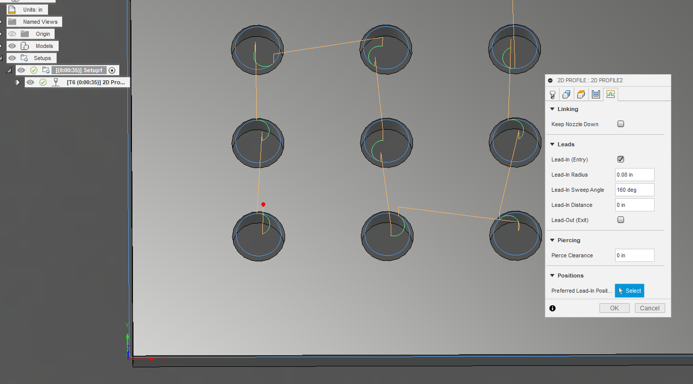
I know. The sweep angle is crazy how it makes it so much larger than you expect. So you can see why when someone puts 0.15 in the lead-in radius it might get excluded when generating the toolpath.
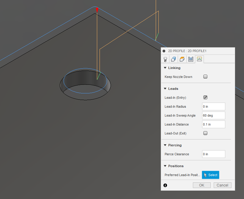
Yes that is true. If the lead-in radius is set to “0” then you would need a lead-in distance. Without lead-in distance you get this:
This post is fantastic. Thank you so much… This is helping me understand the leads and options so much better now. Quick question, how are you able to view those paths in what looks like real time? When my Profile dialog window is open, the paths go away until the box is closed and the paths have been generated. It would help so much to visually see the impact of adjusting those values in real time.
I drew up some little test gussets, and I’m playing with all of these values. I’ll let you guys know how I make out with my adjustments in this area.
I also replaced the bearings in four more blocks, so I’m going to swap those out and check a lot of the other things you guys are mentioning like the lead nut screws, torch assembly, etc… I appreciate that advice. @holla2040 also has me thinking to make sure I start my runs with plenty of air too.
I really appreciate all of the advice. Such a huge help.
We have a large shop compressor but I pay close attention to how often it runs during a job. It’s easy to hit the space bar to pause, aka ‘feed hold’, during operation between cuts to allow the compressor to catch up, the torch time to cool down and your stock to cool off as well.
Good practical advice that I would probably have not thought of.
I am using an older version of this 2 stage 7.5hp 80gal. My wife found a great deal on Facebook. With some cleanup and a spitter it has been an awesome machine, and not as loud as I would think, but when it runs it definitely runs.
Here’s another reason for pausing. I’m using sheetcam which has an option to move all around to spread the heat all over the stock. If you have a lot cuts close together, your metal will get very hot.
This is awesome… Not that you ran into these issues, but the advice. My hope is to do a big cut here soon and I appreciate the lessons in working through a project mid-run.