Do a lot of “dry runs” before you cut to verify what you think should happen compared to what actually happens.
Thanks for sharing Craig, your table looks great!
And some good tips for larger cuts for sure.
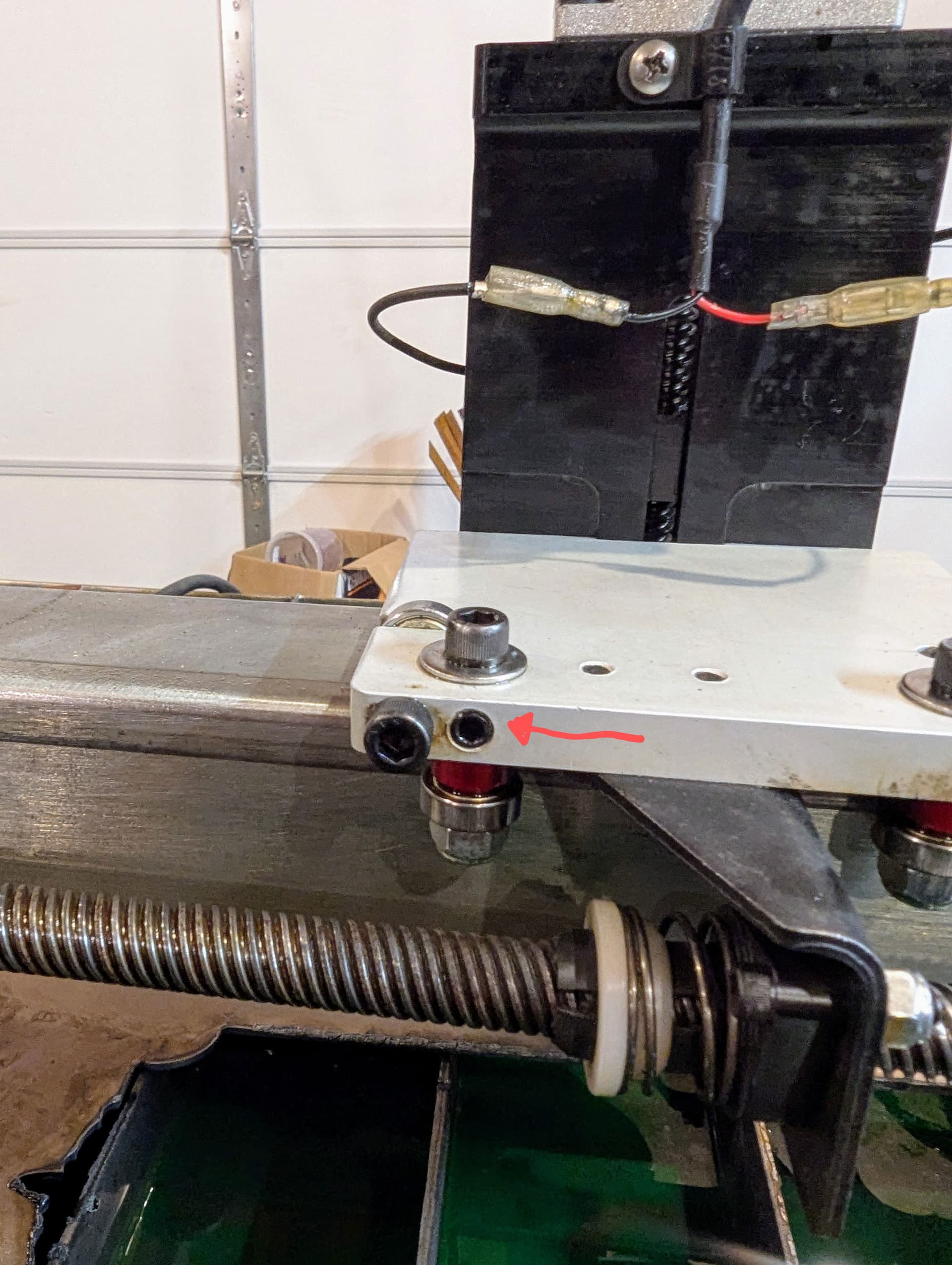
I didn’t make out much better with my leads/peircing, but I did swap out four more bearing blocks, and I think that I found the root of the wiggle! I’ll attach a photo of the set screw that I think was allowing the wiggle.
I need to keep playing with those settings, but if I’m going to post a couple photos of my results. Also, are my amps looking too high/low?
It is magic!!!
No. You actually need to allow Fusion to process the entire tool path. I then go back into the toolpath as if I am going to edit it to show you what my values were.
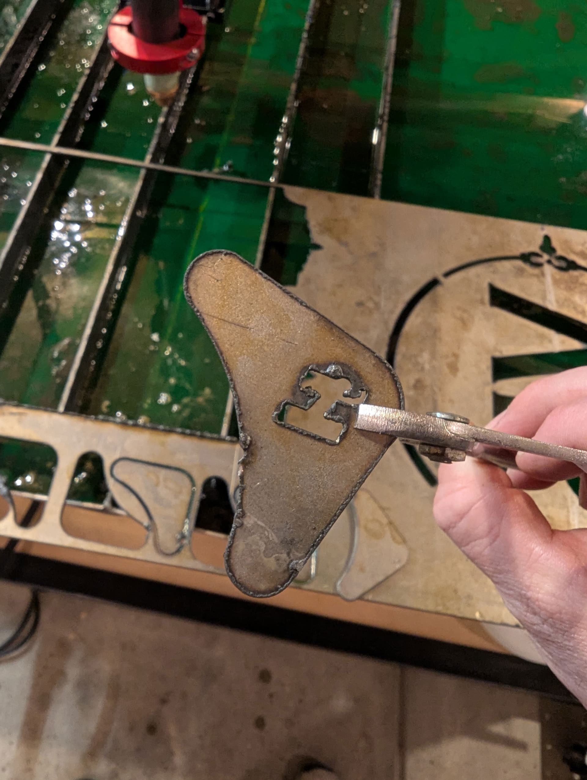
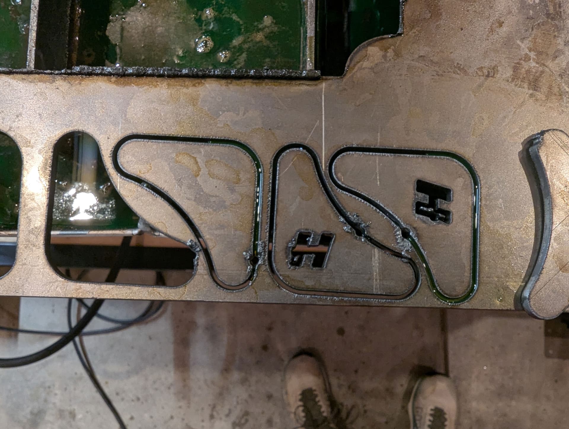
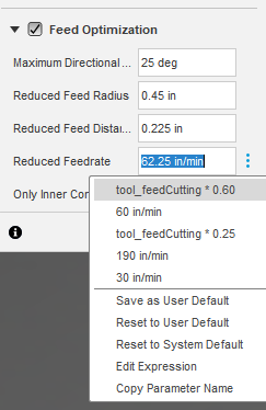
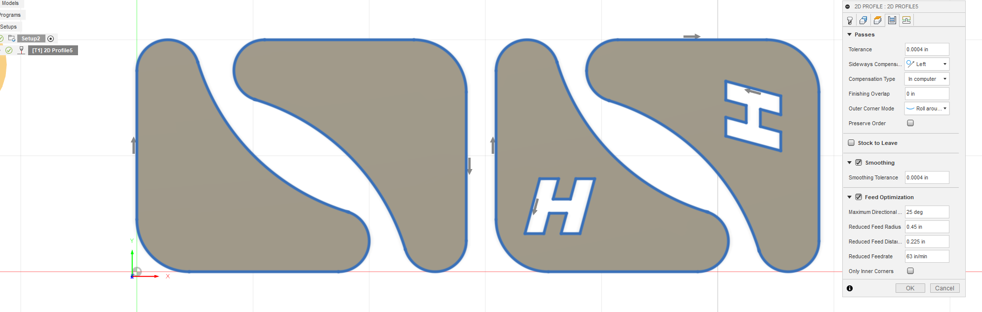
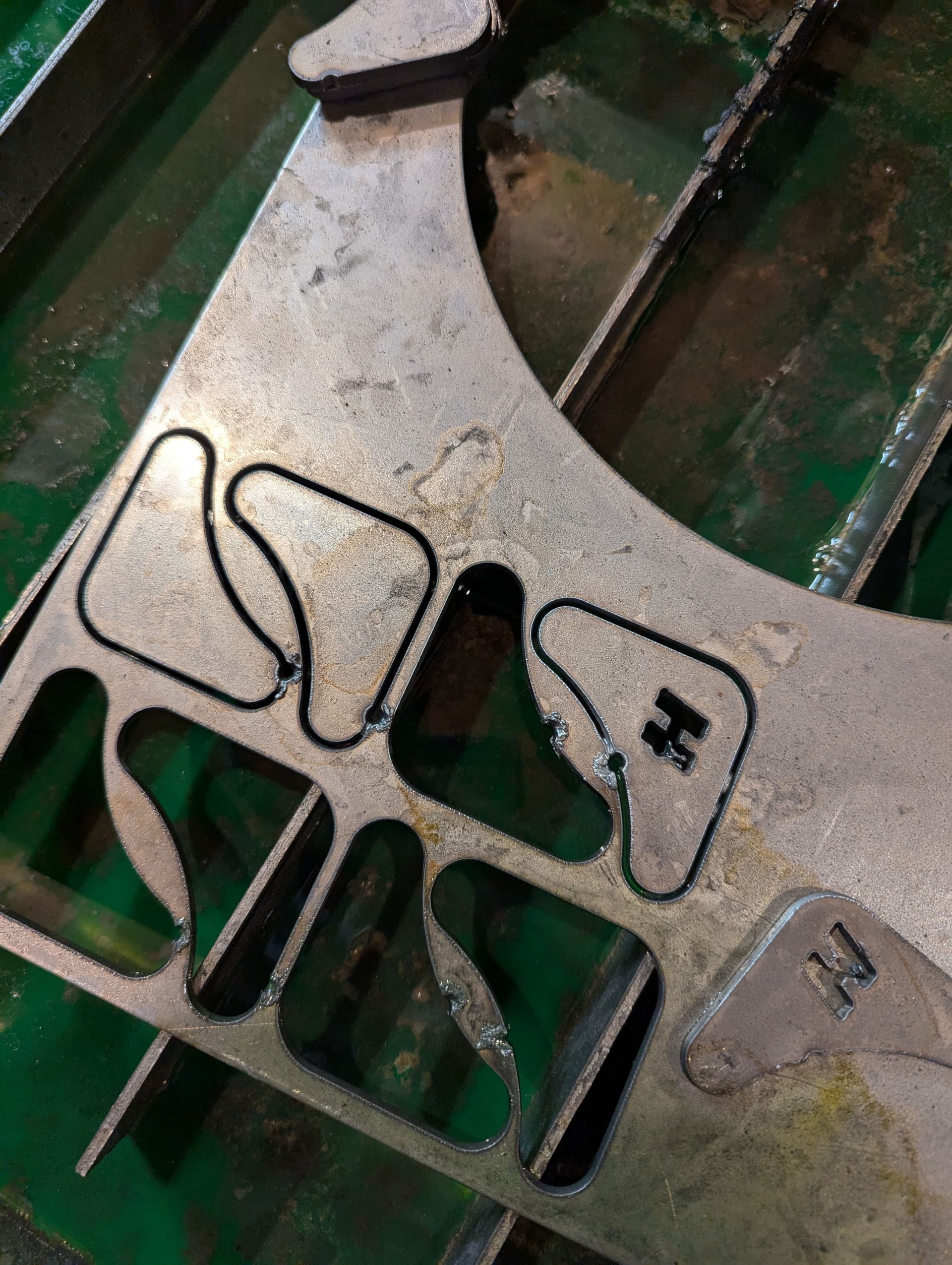
It looks like your speed or pierce/cut height might be off. Notice all the topside dross where your lead-in is. It is getting lots of dross because the cut is too slow, amps to low or cut height too high. But it does match the rest of the cut so it is something to do with the actually process of the lead-in. If you have “compensation” picked, Fusion, by default, sets small arcs to 25% your cut height. Change that to 60% of your cut height.
You got my hopes up. That feels like a more intuitive way to familiarize yourself with how those values work. Having to close out of there, take a look and go back and forth makes it difficult to visualize what you’re doing.
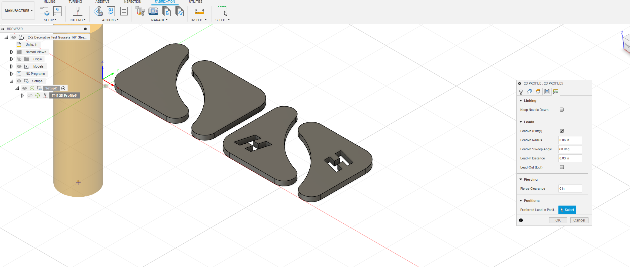
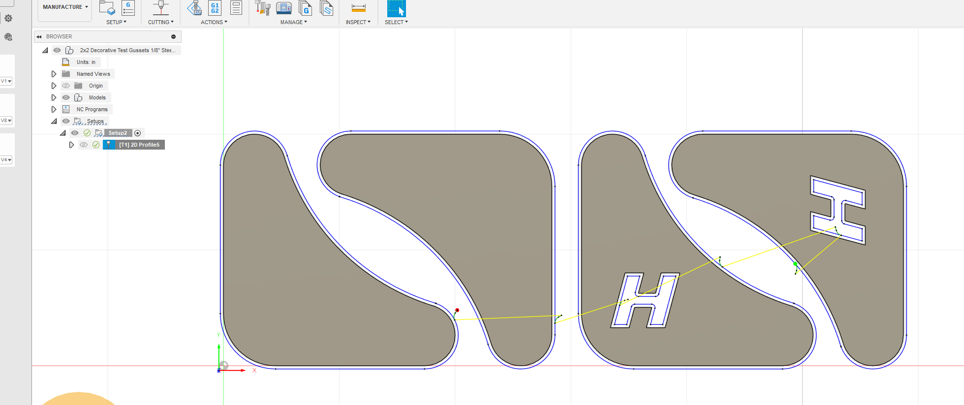
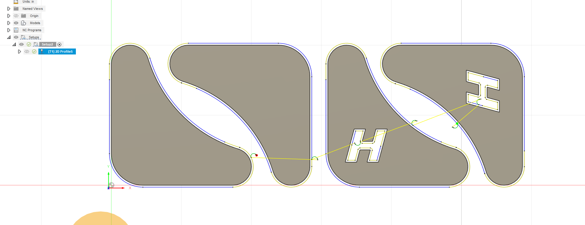
I was a little bummed that these test pieces still showed those pierce marks. I thought in my drawing those leads were enough clearance. If anyone has any suggestions on some better values/strategy I’m more than appreciative.
Thanks again everyone!
You are getting much closer. Notice I edited my last response. See if you have “feed optimization” checked in the tool path.
1 Like
Thank you for the extra feedback. I am making some changes right now. My speed is 98IPM. I wasn’t using Feed Optimization for this because I was scared that it would slow down the machine. If you recommend it, I’ll give it a try though. I am still working on the leads, but I think I’m getting a little closer ![]()
Well then that is not your issue. The primary reason for feed optimization is the limit the bevel on small inside turns. There is something else at play.
Check your cut height to make sure you are where you expect to be. Use Phillips test file for cut height. He won’t mind:
cut height test.tap (224 Bytes)
Load into FireControl. Run it with a piece of metal on the table. It will NOT fire the torch. It will only cycle the IHS system and then stop at the cut height of 0.06 inches + 0.02 inches of backlash/springback. Measure with feeler gauge.
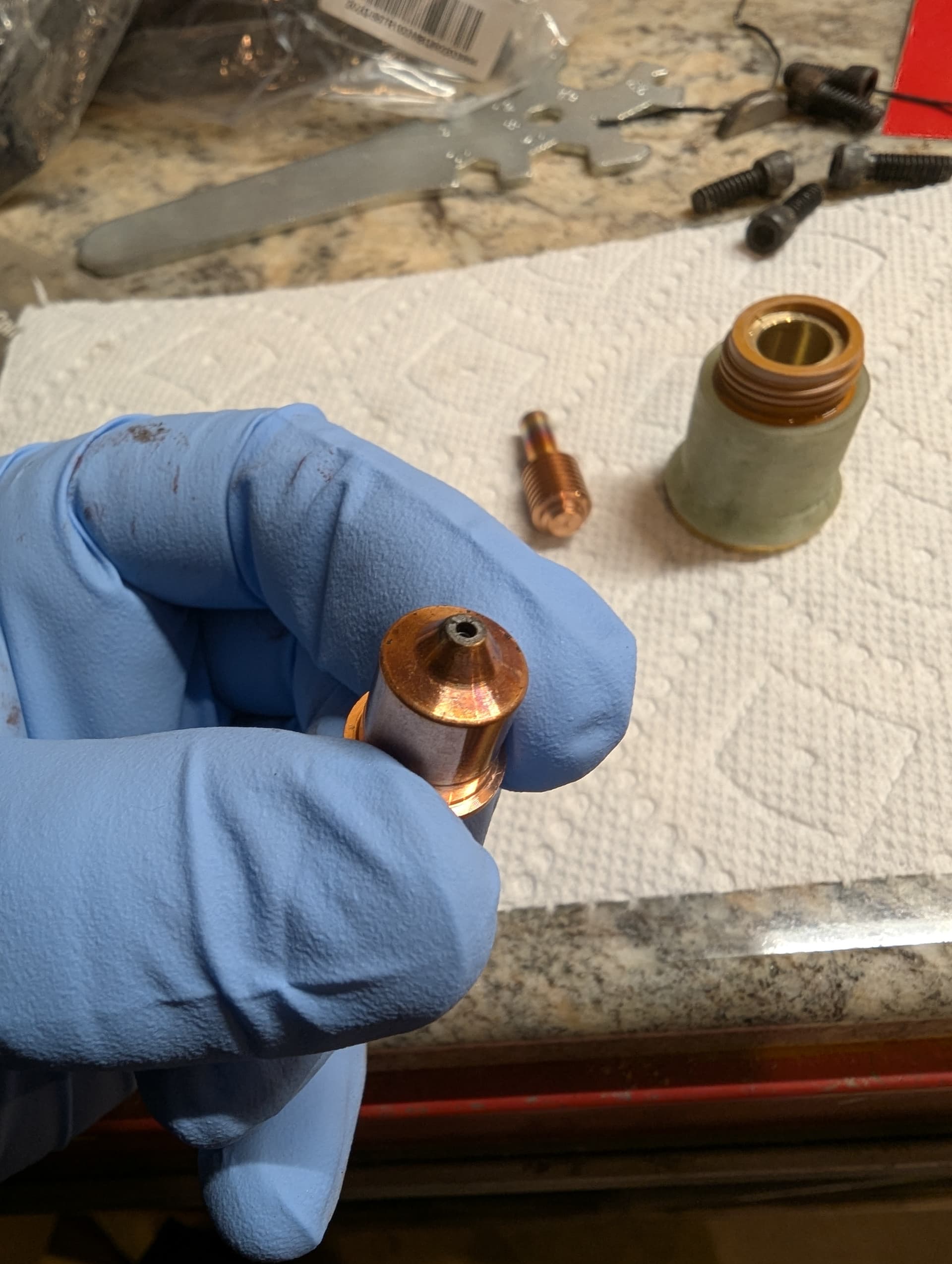
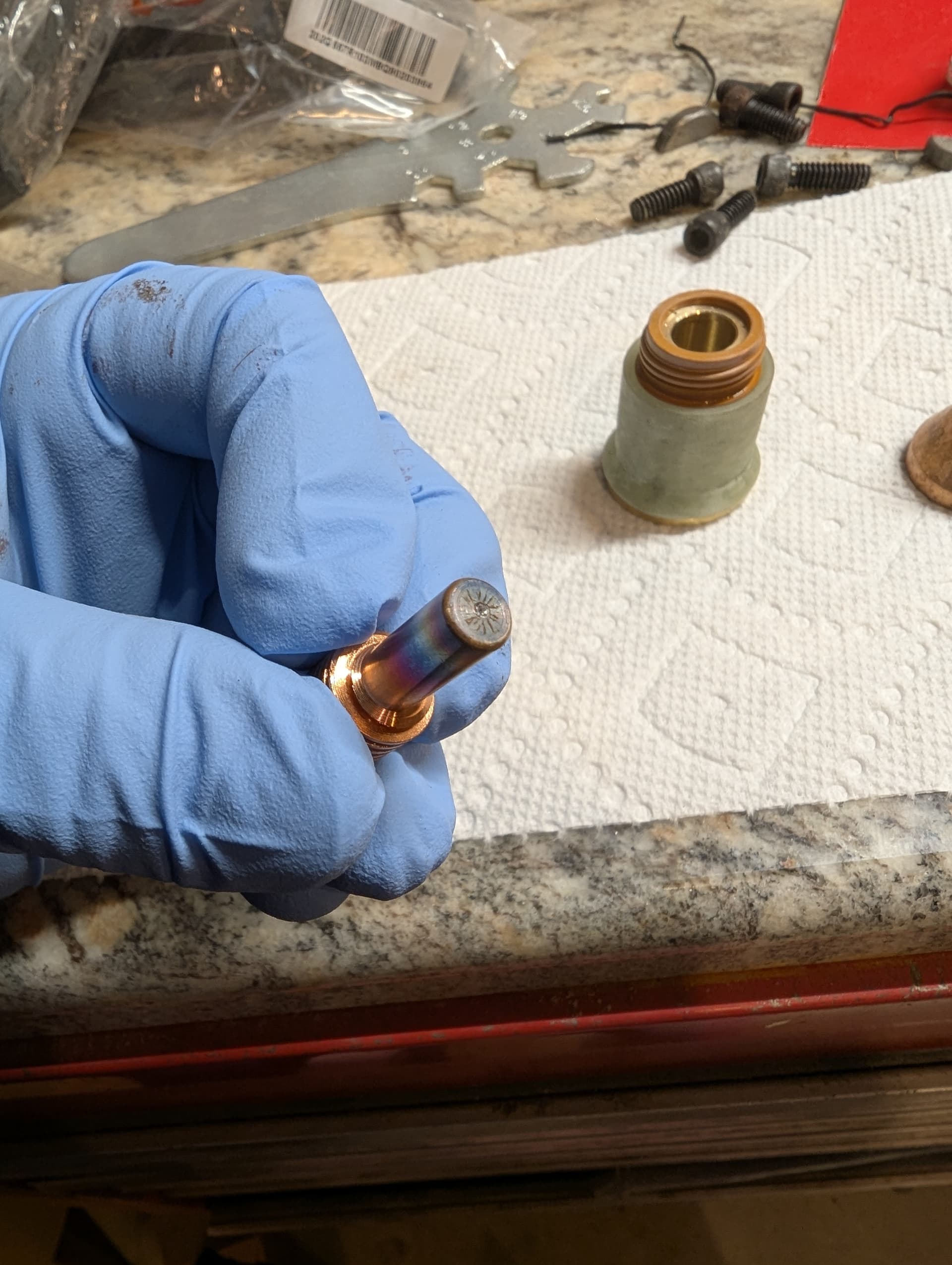
Inspect your consumables: take a well focused photo and share of the nozzle/tip and the electrode.
2 Likes
That set screw is the adjustment for the X carriage bearings, mainly to adjust the tilt of the carriage. Loosen the nut that holds the bearing and use the set screws to move it in or out. There are two there and two more on the bottom of the carriage.
Also check the wheels that roll on the rods for the Z axis. The two on the right side have eccentric axles to adjust them. Loosen the nut and the axle has a flat on the end to be able to turn it for adjustment.
1 Like
If my memory is correct isn’t there a discrepancy between f360 and sheetcam on the IHS cycle? I believe someone also has one created in f360. Maybe we need to fix one from there as well.
I am not sure how clear all this is for you but thought I would break this down a little more.
I don’t always understand things as well as these guys so I will explain like I would to myself.
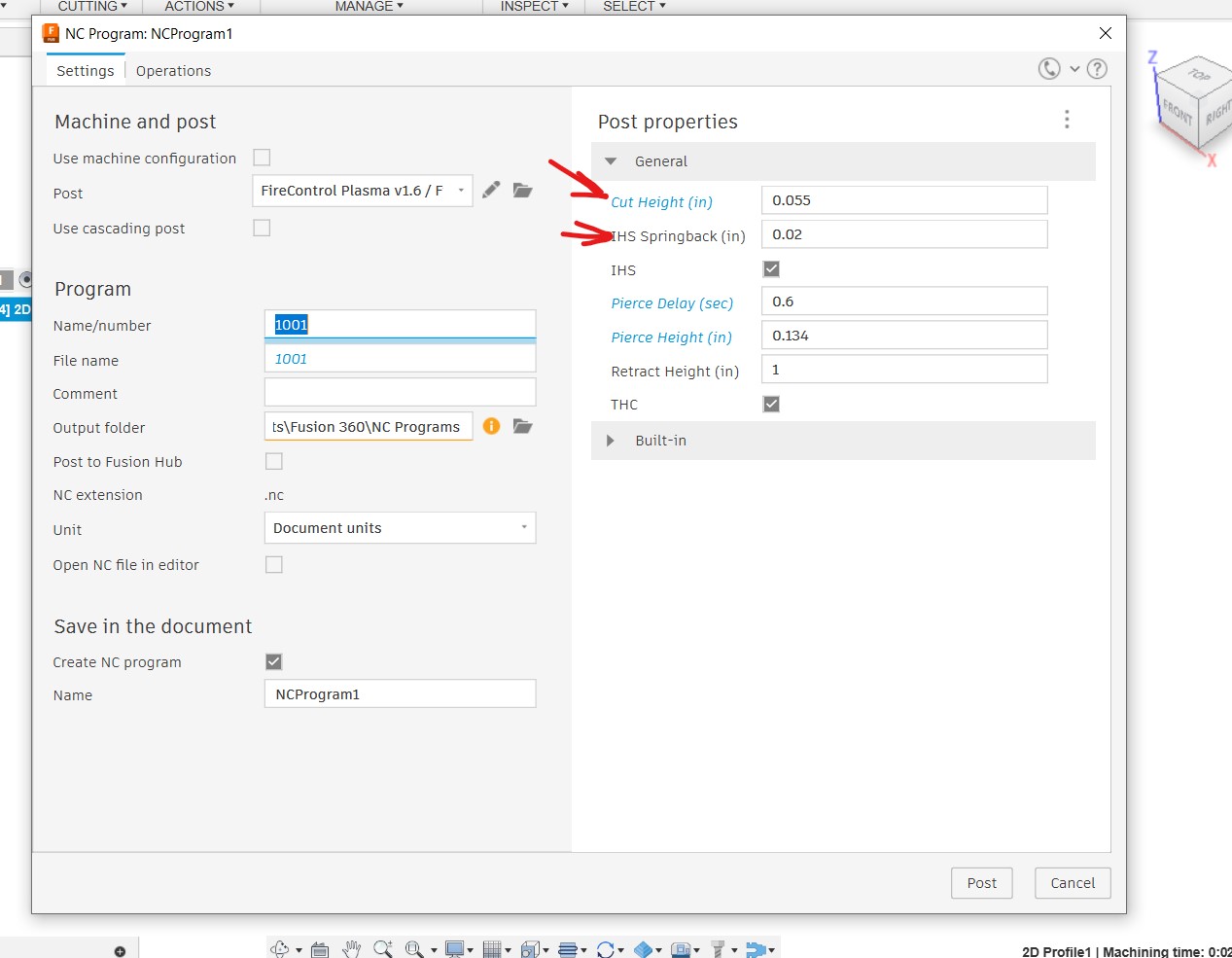
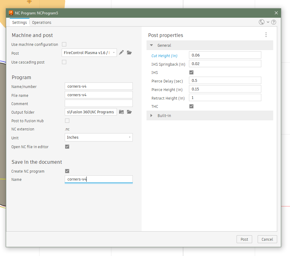
So when you post process in fusion (make G code/NC file/Cut file) you set two things that effect the cut height. One is labeled “cut Height” and the other is “spring back”.
On thinner material, if it is slightly warped when the torch comes down to check the height of the material, it might push the sheet down some and then when it raises back up the sheet will raise up also.
This will skew the settings. When you run the program and check the cut height, this will taake into account the 2 settings in fusion. lets say your CH measures out with feeler gauges at .040 you will need to add .02 to one of the two setting in fusion, and the opposite if to high.
RW45 CH is .060.
I have a RW45 and I cut every thing at 45A Only thing I do is change IPM. not saying that changing amps may not give you a little better cut, but for now I would stick with 45 till you get the basics down.
I hope this helps and does not just add to more confusion! ![]()
Here is where the settings are in Fusion
2 Likes
I don’t know. That is not ringing a bell for me.
But while we are on the topic, if I wanted to make that test cut without the springback in it, do you think this would work? I have not tried it yet:
(v1.6-sc)
G90 G94
G17
G20 (Units: Inches)
H0
G92 Z0.
G38.2 Z-5.0 F100.0
G38.4 Z0.5 F20.0
G92 Z0.0
G92 Z0. (IHS Backlash)
G92 Z0.0
G0 Z0.15 (Pierce Height)
G4 P0.5
G1 Z0.06 F100.0 (Cut Height)
M5 M30
(PS100)
cut height testNOSPRINGBACK.tap (223 Bytes)
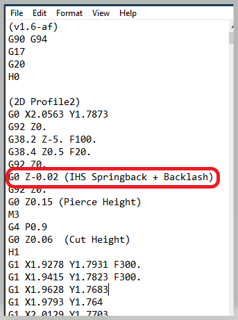
BTW this is how the Fusion post processor resolves putting “-0.02” in the Springback/Backlash line: G92 Z0. (IHS Backlash)
I was thinking someone more familiar with fusion said there was a added extra spring back in the post processor.
I don’t see why it wouldn’t work I probably would have just completely deleted the entire line. Just less confusing for me anyway.
If I get time in the next couple days I will create one in fusion and compare them .
Oh, yes that is true but we are talking about once your gcode gets to FireControl, it behaves the same. So getting a feeling of where your table/computer communicates and results in what cut height was the only thing I was getting at. Once they find out that it is setting the table at 0.06 or 0.08, for example, we would then know how to advise them.
But it is true that the post processor in Fusion is already going to add 0.02 inches to the cut height so when you enter “0” for springback then Fusion adds that to 0.02: 0 + 0.02 = 0.02
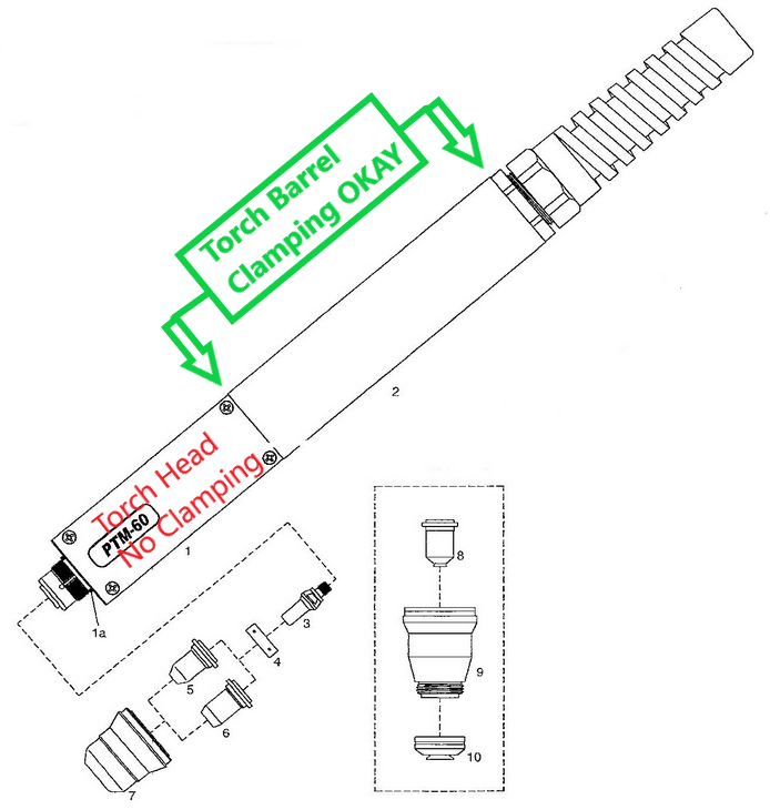
I believe your torch is mounted wrong. The bottom strap should not hit that low.
I will let others weigh in on that nozzle.
Oh not contradicting I am just trying to get my facts straight. I had it in my mind that if someone runs that tap file and finds out they are .020 off. Then they create their work in f360 would they have been off.040 and still off .020 even though they already compensated.
Thank you. There was no paperwork or documentation that I could find on it, and just guessed. That looks like a different torch too, but when I get back out there I’ll see if I can mount it differently.
If the metal plate was thick (no flex to the torch touch down) and it measured 0.08 with your test file then I would use -0.02 in the springback in a true post processing for the thicker metal like so:

If I was planning to cut thin metal then I would allow the springback by entering 0.0 and the gcode will end up having a value of 0.02.
The biggest problem is that when someone expects they need a springback of 0.02 and the enter 0.02 in the “Post Properties” area. They often don’t realize that their 0.02 is going to be added to the 0.02 that is planned and that results in 0.04. When the cut height of 0.06 is expected, they will often end up with a cut height of 0.1 inches (0.04+0.06 =0.1)
In testing I have done in the past, I found that if you put a negative number in the Springback of a larger magnitude such as “-0.03” then it was completely ignored and ended up being 0.02 in the gcode. Recent testing of that theory seems to allow the larger negative number thru so I am not sure on that.
Edit:
I just confirmed. If you put in a springback of -0.04 it will add the intended 0.02 value and correctly puts “-0.02” in the Springback section of the gcode. I don’t know how if the table follows a negative number correctly. I have not tested that.
1 Like
It looks like your pierce delay is not long enough. The cut looks like it started moving before the plasma stream cut all the way through the metal. Try a .8 second delay on material that thick.
The large hole looks like it is being caused by the torch still burning at the end of the cut. I would add a lead out to move that to the waste material.
1 Like