Can anyone here measure the black drains? size, angles and offset from the top. I want to 3d print ones with larger drain tubes.
In my thread I documented the distance down from the top surface and the insert size. That’s probably enough to get started.
1 Like
Check out my thread on this - just drill it out and use 3/4" boat thru-fittings - at $5 each its hard to beat lol.
1 Like
I like your idea, just figure I would 3d print some with larger opening and not buy a drain kit.
Having used the factory drain kit, I highly recommend coming up with your own solution.
The factory injection molded parts had varying levels of warp between the main body and the tabs. No one was sitting level before pouring the concrete and packing the concrete around them certainly caused them to float up. After just surfacing the base plate, it caused enough chips to start blocking the small drains and caused the coolant level to rise above the enclosure mount bolts. I also lost one of the drains when the rubber 90 slipped off during the concrete pour.
My suggestion:
- The drains need to be enlarged to not so easily clog with small chips
- The tops of the drains need to actually be level for good performance. I am thinking about using an oscillating tool to cut off parts of the factory drain lip which stick up and prevent good flow.
- The drains need to be securely anchored to the chip tray so that they do not float / move when concrete is packed around them. Alternatively, the drains could just be the boundary of the concrete slab.
- Clips are moved with the coolant. This means that chips have an equal change of ended up at the rear of the machine where it is a PITA to remove them because of the design of the enclosure. I’m wondering if a large trough style drain, similar to what is sometimes used for concrete shower stalls, only at the front would be workable. That would help move chips to be in front of the doors.
- A plug (coated with mold release) is needed for the epoxy pour that is tightly fitting to prevent ingress of epoxy. I had small amounts of leakage on highly canted drains where one end was well below the level of the epoxy and it oozed in under the tape through the rough surface where the mounting tabs were snapped off (and I had even scrapped those areas a bit with a carbide scraper)
- Having two 90 degree bends in small diameter tubing, with the 90s made out of low durometer rubber being encased in concrete is basically the perfect design to not being able to get a pipe brush through to clear a chip. The factory tubes also appear to be uncoated low carbon steel. One would hope additives in the coolant would prevent serious corrosion but if it happens, the system is unservicable. I would instead suggeset a 1/2 or 3/4 pipe that goes through the side of the chip tray. This would probably have to have to be at an angle as I don’t think it could be plumbed straight down without fitting the flange on the legs. 4x plugs for the factory drain holes in the chip tray would also be needed.
Are you having a bad day? Sounds like you should have ponied up for a Tormach VM series instead. Seems like nothing is working correctly on your machine.
@Bigdaddy2166 This is a thread about improving the design. Its great that you are happy with your build but I note that you do have other threads in which you have discussed modifications.
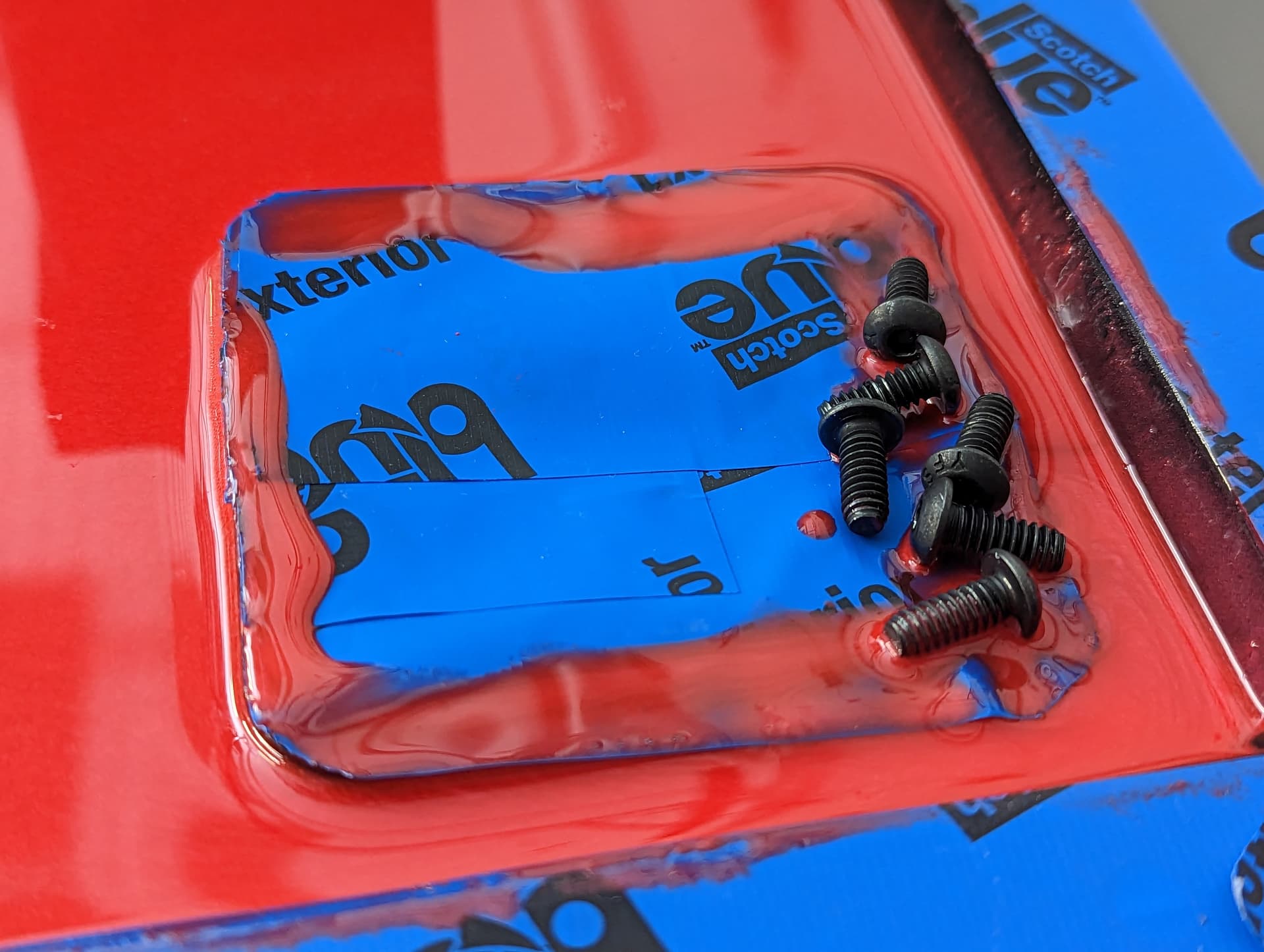
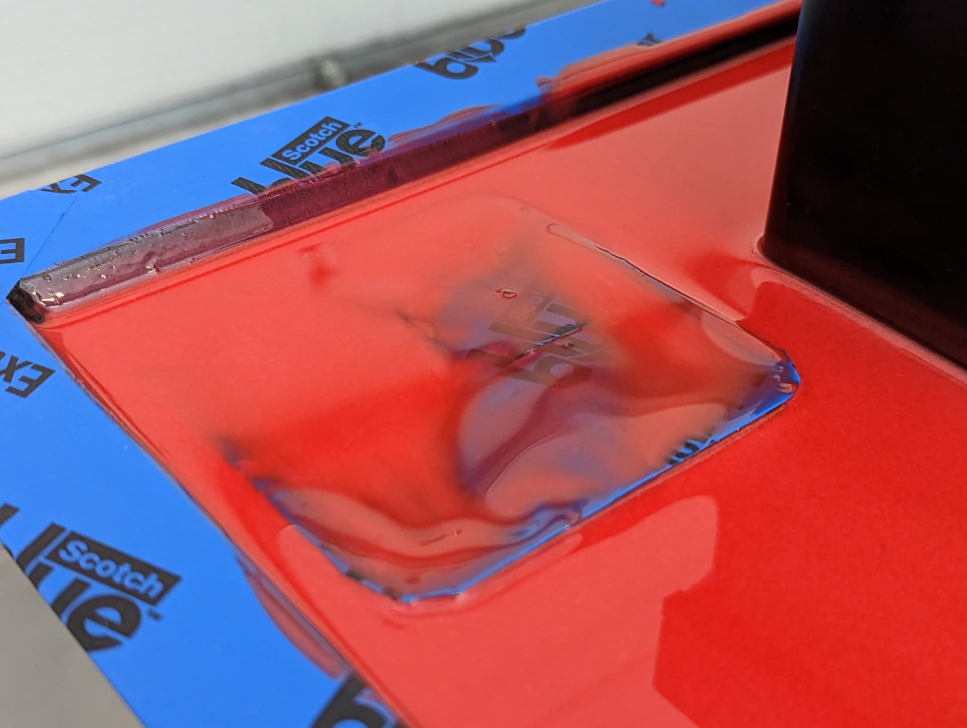
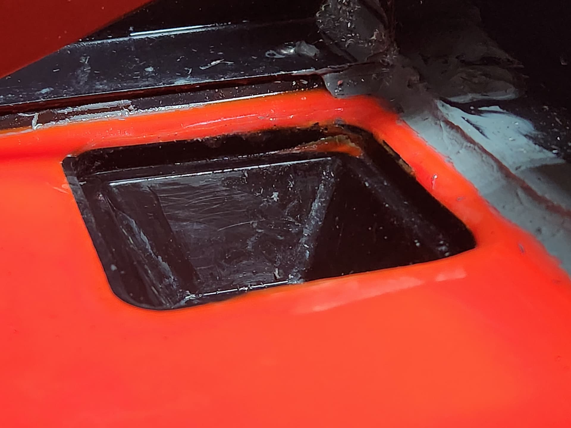
None of my drains were level before the pour and they were worse afterwards. The extent only really became obvious at the epoxy coating stage. These two are the worst examples. The screws were added to try to keep the tape from float off completely (there was a second layer of tape inside the drains as a backup, which saved that one). The chip tray was leveled edge to edge with using a starrett 98-12 on top of a cheap 4’ construction level.
If I was to do this build again, I would definitely revise the drain design.
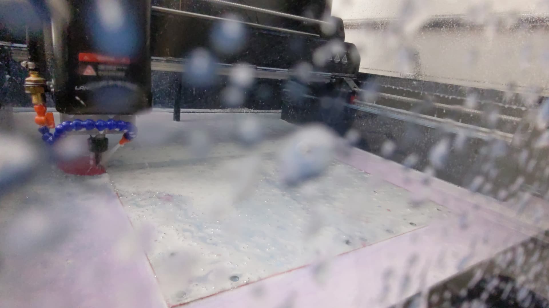
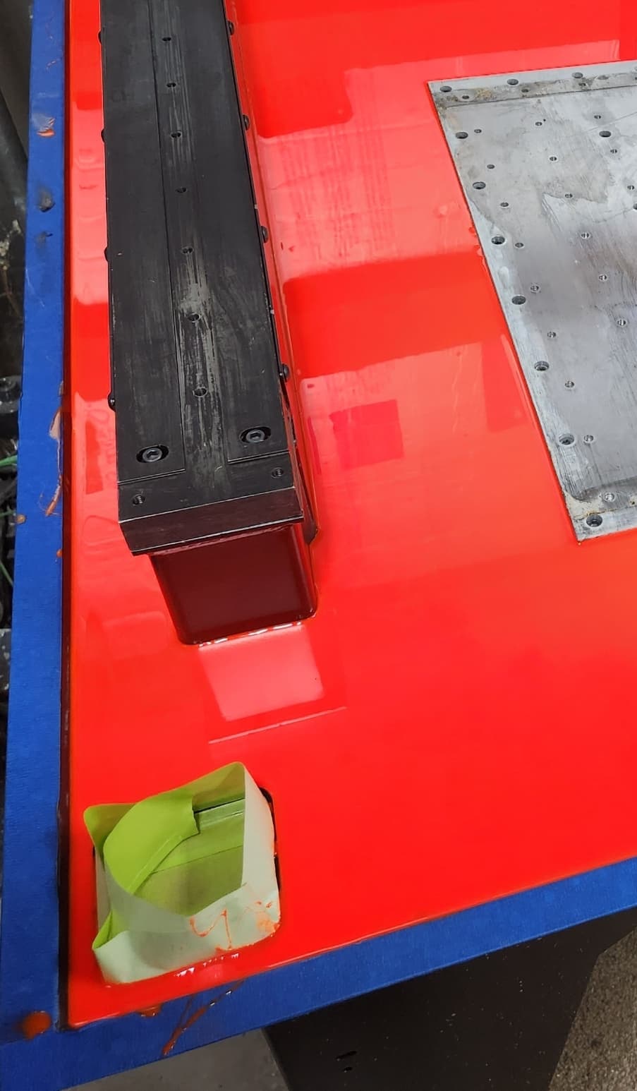
This is the first pass of leveling the base plate. I don’t seem to have pictures of the later stages. This shows the level coolant was rising too before there were significant chips flowing to the drain covers. Drainage is no doubt better with 4 functioning drains instead of 3… but I’m more or less stuck with 3 at this point as the factory design is serviceable after install. Later on the coolant level rose over the bolt holes in the enclosure and started leaking out. I suspect this was because the assembly guide has the serrated nut on the inside and I think this provides a path for small ammounts of coolant to leak out directly around the screws. I’m planning to eventually replace the enclosure mounting screws with M6 screws, with the nuts on the outside, and a crush washer on the instead (1/4" crush washers don’t seem to exist?).
I agree your drain installation doesn’t look to good. Why are they angled back and to the side. Is something hold them underneath?
The coolant in my machine never gets close to coming up to the enclosure flange. Heck thats almost 1/4 to 3/8 deep…
1 Like
Are they blocked? Heck two drains should
be enough to handle the coolant flow.
The tabs were all visibly warped on my drains and were not level before starting the pour. Some copies were worse than others. I believe this is an inherent issue with the shearline V injection molded into the part. The problem got much worse when vibrating the concrete (I used an electric vibrator not realizing the drains were going to float up).
One drain is blocked as the elbow on the drain came off during the concrete pour and I didn’t notice until well after the fact as the drains were taped over. The other 3 drains seem to work normally other than 1 drain being very slow as the fluid must flow in from the outside edge because its unlevel. That is the drain I’m thinking about taking an oscilating tool to to try to get the “inside” lip down closer to the epoxy level.
Honestly, I would be surprised if many people didn’t have problems with drain level as the tabs are intentionally weak. I think the design would be greatly improved if the drains were larger and secured in place with fasteners below the level of the concrete.
Grind down the edges with a 90° 2" air grinder very carefully. I use a piece of scotcbrite in each drain to keep the chips out. Seems to work well.
2 Likes
Yep, grinding down those edges is a must.
I made tape “dams” when doing my epoxy because my drains did the same tilt thing.
Took a Milwaukee rotary tool with a cone shaped grinding stone and profiled any raised epoxy edges afterwards.
My front enclosure also leaked, but a quick bead of silicone across the front seam corrected that. For good measure, I also put a dab of silicone under each fastener to make sure nothing was sneaking through there. Zero issues with draining since.
@safety3rd Geat choice of color on the epoxy by the way! ![]()
2 Likes
As a point of reference, I also did the “dam” with tape around the outside edge of the drain, and then ground a taper with a die grinder after the epoxy set. It seems the epoxxy llikes to climb the tape and leave a ridge.
I relocated my drains and mounted them temporarily using plywood, and then spend a lot of time getting them perfectly level in both the x and y directions, and at the proper level relative to the baseplate. That work paid off, I have no pooling except if the chips pile up and plug the screen. I agree, the design of the drains is not great, there is a lot of room for improvement there.
That being said, I also relocated the drains and put in 3/4" tubing with no right angles before pouring, so the fluid can really get out of the enclosure (I documented that in a seperate thread - Mods thread - I know it’s a bit late for you do to that, you can modify the drains after the fact but you will need to drill out the concrete - a 3/4" hole is not hard to drill with a good concrete impact drill, it will go right through the concrete and the sheet steel. I was thinking this might be a solution, just drill a hole and epoxy a large PCV tube inside the hold in the concrete. I have done this before on construction slab work, should work here,
Cheers,
Mike
2 Likes
I have been thinking about trying to drill out the blocked drain but it is, of course, in the rear and difficult to access with the enclosure mounted. The main concern I have is making a mess out of the chip tray as the bit would need to break through the angled side of the tray. Your drains are in a much better position.
I am also thinking about cutting an access window into the rear enclosure panel, which would make drilling out the drain easier. I received some router cut PC panels from sendcutsend last night to try to rework the leaky doors. If that goes well, I will think hard about how to put an access port into the enclosure.
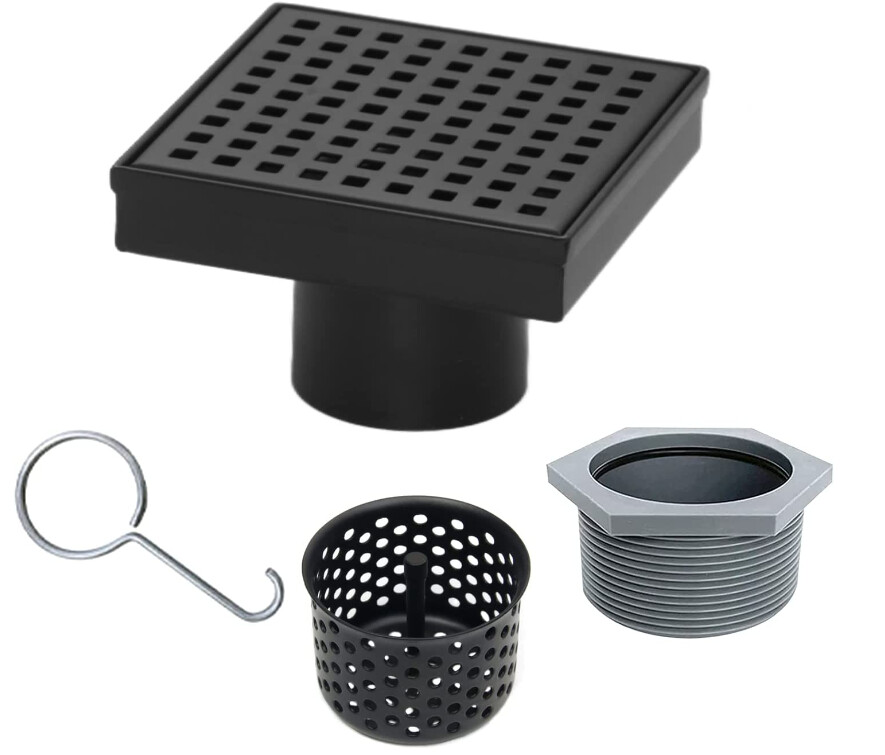
I picked up a couple of these shower drains from Amazon. I’m hoping they will be pretty robust since they are stainless and by running the drain straight down through the bottom of the machine and having externally run coolant return lines it will be a more effective drain system. I’ll put a scotchbrite pad in the drain for a chip filter too.
3 Likes
Just to throw it out there, sealing washers are available and pretty cheap up to 1" on McMaster.
94709A214 for example.
1 Like
Hey Carter,
We need your e-mail and password to see the McMaster part. Please post. ![]()
4 Likes
Funny guy!
I don’t own an MR-1 yet but as I was reading this thread I thought the same thing. Why on earth put the tubes and elbows in the concrete instead of just going straight through the pan and then put the tubes under the machine so you always have access. Do you pics of your finished install?