Crossfire Gets An Upgrade - Floating Z Axis Installed

Here is the dxf file for the stanchion plates. These plates offset the Y axis 3.125" to get back the full cutting dimensions when adding a powered Z axis. This is what worked my machine. The layout can be adjusted as necessary.

Stanchion Plate 3.125 Offset.dxf (4.1 KB)

@TeasleyFamilyCrawler

2 Likes

ok thank you for sharing your design.

1 Like

is there a way to add limit / stop switches on the ends of the stanchion plates so the bearing carriages won’t slam into them?

Yes, search youtube for user: tooljunkie

hey @Burgs04 any chance you can post a whole list of the parts and everything you needed to purchase from the electrical connectors to the motor and hardware? thinking about making up one of these and just curious exactly where to begin really. I have a mill and lathe for making most of the parts I need for mounting stuff but hardware wise a little jumbled… and im an idiot when it comes to electrical so a z drive 101 for dummies would be amazing lol. regardless, awesome work here, super jelly toast!

2 Likes

Yes! Amazing! Thanks a lot my man!

If you use port 3 pin 6, use a relay to switch the -5v pin from the remote control socket to the correct pin it works for TORCH OK. I think i will connect a relay to a E-STOP

Hi! I have been reading over the google doc, and trying to figure everything out before I order stuff. It looks like all I need parts wise is the screw/stepper, the motor driver, and some wiring? I am confused by the write up, and I am not following it, and there seems to be 3 different versions in the same file… Could someone help explain it to me?

OK, I read some stuff wrong… and realized what was going on… it looks like the THC the OP is using, isn’t the PROMA COMPACT THC, but it is a different one… will this work the same way as the one that tooljunkie uses/made??

Having read this thread and seeing all the action with the Pro, it was very clear to me that CF original really needs a Z Axis and possibly THC. Inspired by @Dicky 's work and @Burgs04 original work, I decided to move in the direction of, at least, adding a Z axis to my 2x2.
I didn’t care for all the weight of the Z motor & drive being at the top of the gantry so decided on a belt driven setup where the Z Motor is supported by the top of the original Gantry bracket and the Z Gantry travels on Openbuild’s V-Slot linear rails. The belt is a standard 2mmx6mm GT2 type strung between the drive pulley on the NEMA 17 stepper and an idler pulley at the top. The belt is bound together with a 3D printed clip that looks like this:
BeltClip
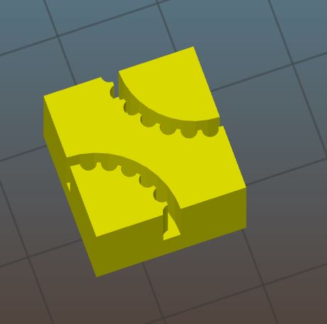
This serves to not only tie the ends of the belt together, but forms the lower part of the floating switch attached to the gantry plate. The switch is also 3D printed and looks like this:


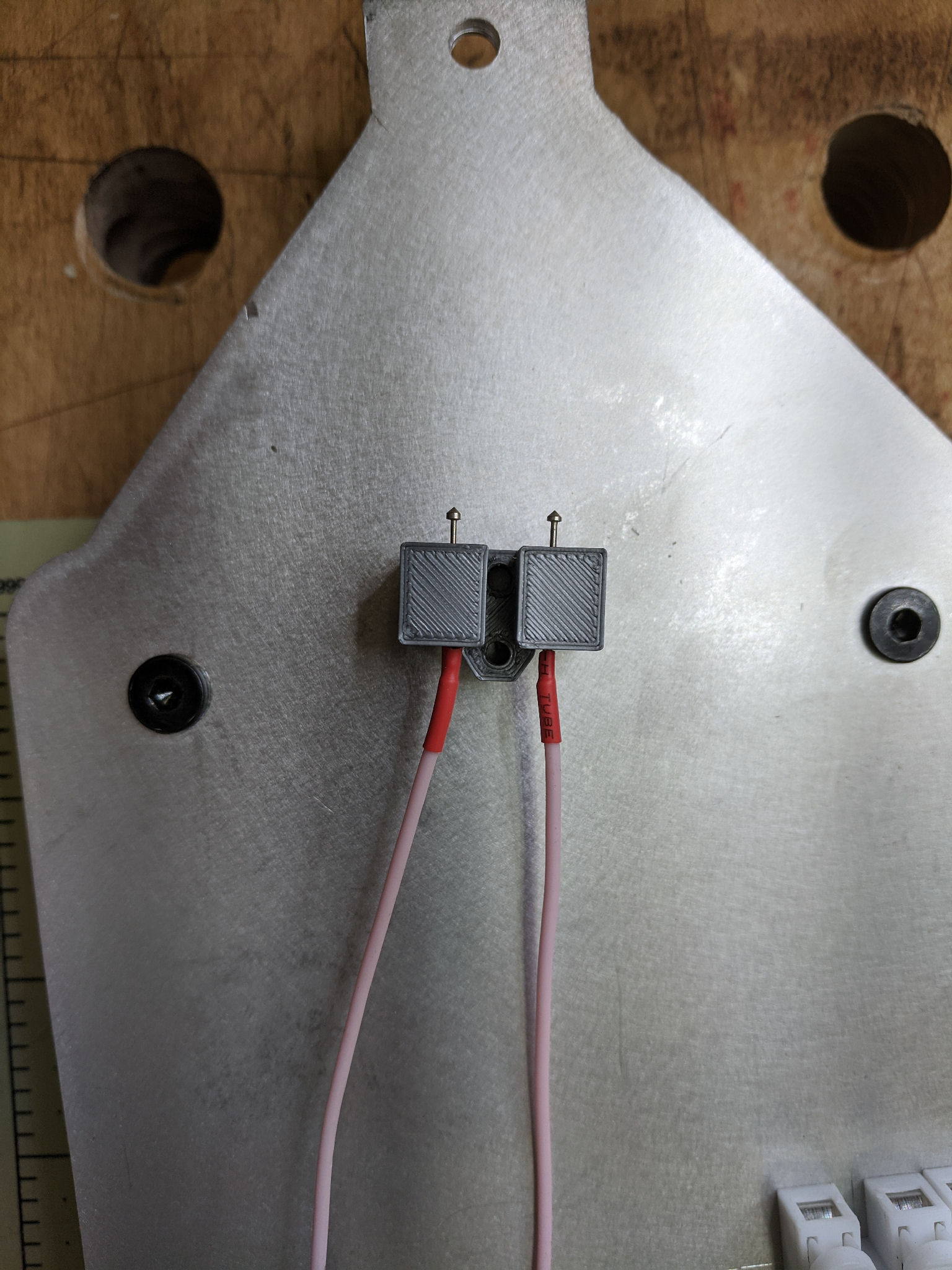
There are two contacts made out of ‘pogo pins’ which are used in electronic test fixtures. The pins are spring loaded and the two pins support the weight of the Gantry and Torch. The belt clip is covered with copper foil and makes the closing side of the switch. When the gantry is lowered into the workpiece, the gantry stops moving and the belt clip separates from the switch contacts. Easy peasy!
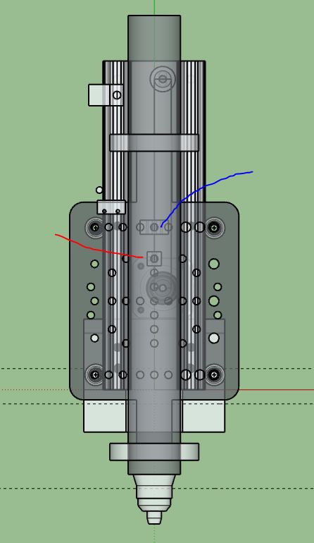
Here is the xray view of the design with the red line showing the belt clip and the blue line showing the contact block.

Finally, here’s the whole smash in the homed position:

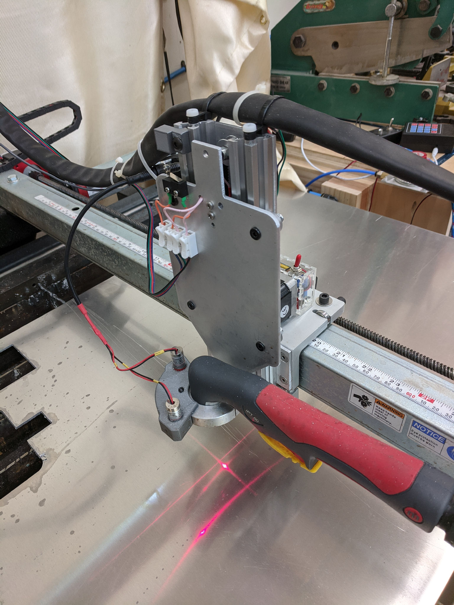
and at the pierce position…

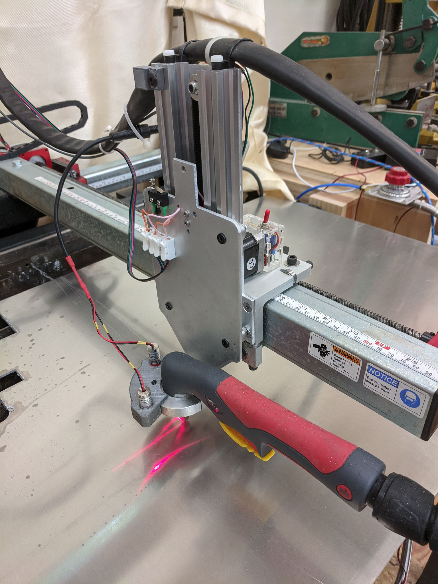
Note that the cabling is not final, I’m debating whether to keep the cabling supported by the torch cable support or add drag chains… the jury is still out on that question.
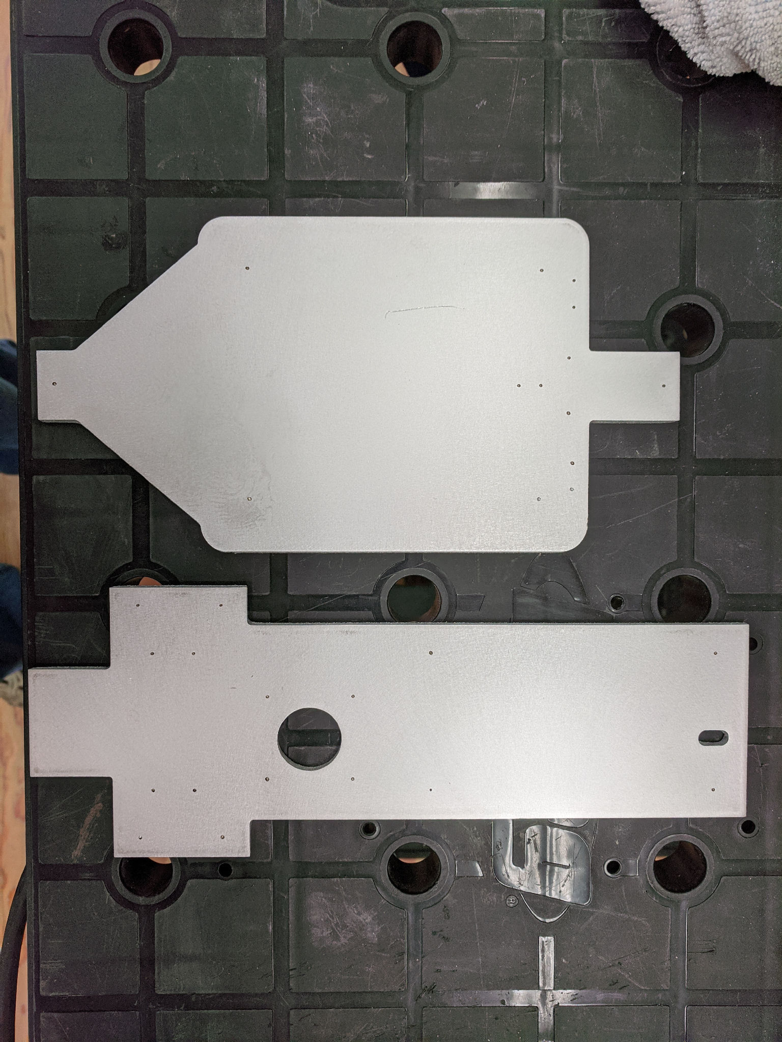
As a bonus, in trying to decide how to drill accurate holes for the gantry (especially the wheel posts) I experimented with ‘marking’ the hole positions, rather than cutting them with the torch. This turned out much better than I expected as shown below:

There you have it! My first experiments cutting with the Z axis were great! I did some learning on the first set of cuts, mostly related to pierce timing, etc, but I think I’ve gotten the best cuts, at least in steel, that I’ve ever gotten.

If you have any questions, as always, ask away!

2 Likes

It looks like you used a buck converter to drop the voltage down to 24V so you could feed the corssifire control board and use the inputs. Have you had any interference problems caused by noise from the buck converter? I am about to try the same thing.

1 Like

No, I kept the 5V hookup that was in the original controller (from the USB port), but followed @Burgs04 method and jumpered the current limit resistors on IN1-IN4 with 820ohm resistors (805 surface mount fit nicely on top of the existing 3K ohm resistors). This gives me more than enough current to trigger the opto isolators.

I may replace that wiring with an isolated 5V supply at some point. I’m not too keen about drawing that much current from the USB connection. But, for the moment, it works.

So my Z stepper driver is powered from the same 36V supply as the other steppers, but the NEMA 17 motor only draws 1.5 A so I think I’m still safely within the 10A limit on that PS.

That’s the method @Dicky uses and he hasn’t had any issues with that as far as I know.

Thanks that is good to know. I’ll try it and if I have issues that will be the first thing I swap out. Just to clarify you put the 820ohn resistors in parallel with the 3K resistors? If so then those pullups are only using 7.7 mA for each input.

Exactly right. I ran a test before selecting the resistors and drove the return leg from my limit switches to a negative voltage to see how much current I needed. I was amazed to find that I only needed another 0.6V to trip the signal. I was measuring the current, but I’ve forgotten the exact number, but it was below 2mA. @Burgs04 used 680ohm in parallel, but I decided that 820 was more than enough margin.

These ones right?

1 Like

Yup, they’re the ones. Once you put the resistors in parallel with them then grounding (to DCM signal), you’ll get an Active signal on the corresponding input.

As far as I can tell, the only reason that the ‘24V’ signal is jumpered to the 5V pin is that they used a 5V reed relay for torch firing. Dicky replaced that relay with a 24V relay, but it’s a slower relay. In my case, the reed relay works fine for my cutter, but I could get a 24V reed or add an isolated 5V supply now that I’ve added the resistors. I would rather have the switches AND loads on an isolated supply rather than the USB port! That’s the whole reason for the isolators in the first place.

1 Like

I had some 680 ohm SMD that I put on top of the 4 resistors. Now I need to find the input pin config for mach 3 to get it set up so I can test.

…and found them and they all work. Thanks for the help.