Beginner installation

Hey Folks, I recently purchased the Langmuir Crossfire Pro and have spent the last month or so setting up the complete assembly. I had limited knowledge on the system going into the purchase but thanks to this forum and several of the members, I have been able to learn a great deal about what is needed to run the Crossfire Pro and some good practices. I will be using the Primeweld CUT60 Plasma Cutter along with a 60Gal Husky Compressor and have intentions of working between 1/8" to 1/2" mild steel as well as playing with some aluminum at some point down the road.

What I have done so far:
-Purchased plasma cutter a few months ago anticipating purchasing a table

-Purchased the Crossfire Pro (found a gently used one on Facebook Marketplace that had already been assembled and the previous owner had gone up to the XR [that is one good looking table])

-I was fortunate that the previous owner was very willing to guide me through the basics of using the crossfire pro and the FireControl software. I was able to retain some of what he said for the future but there is still some learning curve left to travel.

-Realized that I needed a LOT more air than I currently had

-Purchased the Husky 60Gal Compressor. Was wanting to cut a corner and try to make a 30gal work but bit the bullet as it became very apparent the importance of appropriate air for the system and in the long run, having the bigger compressor would be beneficial. Buy once!

-Realized that a simple hose connection from the compressor to the plasma cutter would not suffice

-Purchased the RapidAir MaxLine 3/4 hose kit, a filter/regluator combo, several additional fittings/valves - saw several youtube videos of this setup used in different ways and felt confident this would work for my application.

-Got the compressor hardwired into 220V.

-Got the air line system installed - shut off valve immediately out of the tank to one of the drain stations on the rapidair system. Routed the hose up to and around the ceiling. Plugged in a T Joint. Down the first leg I inserted the regulator/filter combo then into the 2nd rapidair station. This leg will be for the crossfire pro. Down the second leg, I continued along the ceiling to the far corner of the room, down the wall, and into the 3rd rapidair station. I will use this leg for general tire inflation or possibly air tools in the future but may need to further modify at that point. Oil/lubricant/still need to do some figuring if so.

Also replaced the drain plug at the bottom of the compressor with a brass 45 and a hose bibb for easier draining. Found that the original drain was not super easy to access and also got clogged at one point during pressure testing. Tried to repair then got a leak and said screw it.

-Ran several air system leak/pressure tests to assure I wasnā€™t losing too much air. Took about 3 tries to get everything sealed to a reasonable point. I still have some minor leaks in a couple spots after doing soapy water tests but am holding 125psi in the air system pretty steadily for about 2 hours now with negligible loss. For my hobbyist use, I think that will work good enough to get things going.

-Water leak tested the table multiple times. The previous owner added a hose bibb and hose to one half of the table. It works good enough for now but draining the other side of the table takes a little extra effort as the drain on that side is still plugged and the lip where the two pans join in the middle still remains. He used the provided sealant to seal the two pans together from the bottom and had also used the sealant to join the pans to the table. Not bolts/screws used for pan to table mount

Would be nice to know what kind of sealant that was as I have not found the specific brand/type anywhere online up to now

He noted that there were some leaks from the upper section of the right pan. I found that this was happening at the outer most and second outer most bolt holes in the pan. I went ahead with removing all of the sealant between the pans and the table and went to using 1/4" self tapping screws and washers. Had some laying around so got them installed only to find after 24 hours these were not stainless steel and 2-3 had completely rusted the head off the screws. Got some stainless steel 1/4" screws and washers and reinstalled these along with some 3M Fire Barrier Sealant. Saw a few different options used and my thought process was that this should hold off water and additionally will expand when heated rather than risking losing its grip when heated like some other options had. Did this all last night and will be water leak testing again later today.

-Made a simple circle sign design on fusion 360, input the GCode into FireControl and did a dry run without the plasma cutter attached to test the x and y axis travel. x axis has a little vibration at one point so will hopefully get this ironed out. Other than that, it ran smoothly.

-Clamped the torch to the z axis and did several clockwise AND counterclockwise laps around the table assuring the wires would not get too close at any point during cutting. I am now at 4-6 inches above the work piece minimum to the wire at any point on the table to prevent burning the wires or snagging them on a sharp edge.

-Spoke to Primeweld about a use chart. They provide a decent reference guide in their manual but was curious on the Kerf Width and the Nozzle Diameter. Found out that the Primeweld Cut60 comes with the 1.1 nozzle and they recommend doing a 6" cut to dial in the kerf width. whatever the width of the line is, thatā€™s the kerf width. Also saw on here that doing a 2"x2" square cut and then measuring length/width of the box will help correct variance of the Kerf width given the nozzle and sheet metal thickness used. Still need to dial this in but at least have a gameplan there.

-Because I want to do 1/8" and 3/8" steel and this is not on Primeweldā€™s chart, I put the given thickness recommendations into a spreasheet, graphed the lines out of the known options and then estimated what those amperage/psi/ipm values need to be. Will test these out but at least have a starting point.

-I also ordered some PlasmaGreen 9010 to use in the water to minimize draining/cleaning needed. Should be here in the next few days.

Now that weā€™re up to date, I will be coming back with some updates on getting the system going and experiment with different settings. Hopefully I can learn quickly to minimize the material costs once I start cutting things out. I am just getting started on the journey so I am sure some of this is practical to several users but maybe this will help some newcomers to the group and my thoughts and answers to questions can be beneficial as time goes on.

My first question to the experienced users:
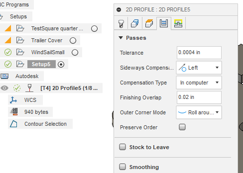
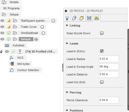
Assume I want to make a 4"x2" bracket with a 1/2" hole in the middle. Both the perimeter and the hole diameter are critical dimensions. From what I have seen, you can cut through the center lines, on the outside of the center lines, or on the inside of the center lines. For the perimeter, I would probably want to cut on the outside. For the hole, I would want to cut on the inside. Is there a setting in Fusion 360 that can assure both inner and outer critical dimensions are held or do you have to pick one?

Would love to learn more technical strategies for getting optimal cuts.

Thank you guys!

3 Likes

Welcome to the forum! For an outside cut, you want the cut line outside your design (the kerf should be on the outside and moving clockwise to the line). For an inside cut you want the opposite, cut inside your design line and the cut moving counterclockwise to the cutline.

If you use a CAM tool like Sheet cam then a design with both inside and outside cuts will automatically be cut in the correct direction IFF you have cut in ā€˜outsideā€™ direction with ā€˜reverseā€™ direction checked in your tool setup.

3 Likes

If you have the part extruded in Fusion, when you select the part to cut out it will automatically bias to the inside on the hole and outside on the square. If youā€™re just cutting a sketch, you have to pick which side you want it on. You only have to change the left, right, center of the line if you want it to cut that way for everything.

3 Likes

@PlasmaDonor welcome to the forum, it sounds like you are off to a good start!

Are you saying the original owner didnā€™t use the provided screws to attach the water table to the frame? I would definitely use the fasteners (sounds like you have?) as the frame relies on the water table to add rigidity and keep the frame square. I know some of those adhesives are pretty good. I have used them to attach aluminum skin to enclosed trailers I have repairedā€¦ but having fasteners will add allot of rigidity to the system.

This is the method I use thanks to @TomWS and @TinWhisperer suggestions. It works much better than a straight lineā€¦ at least with my eyes. You will need to set it to cut the center (default is left) of the line when you run it through the CAM in Fusion. The difference between your design dimension and your cut dimension is your kerf width. Your kerf width will vary due to several variables including but not limited to tip size, tip age and material thickness ect. For this reason, if dimensions are vital, I do a kerf test prior to setting the kerf in CAM.

You can order lower amp tips for your PW cutter if you want. I have 1.1 and .9 tips on hand.

Using the book values, I use liner interpolation to get a starting point for values not on the list (which is what you are doing graphically) and it works well. Usually, it gets you as close as the chart does.

You can choose which side of the line you are cutting when you select your 2d profile in Fusion 360.

If you extrude your object, it generally will automatically assign which side of the line is cut and it is usually correct. You can change the side it cuts by clicking the arrow.

I recomend you go through the Langmuir tutorials and watch the practical fusion 360 videos by @TinWhisperer

4 Likes

Welcome. You have already gotten great advice from the people before me.

All I will add is that you can confirm which side Fusion is going to design the gcode by running the simulation. You may need to zoom in on some of the small areas to verify. Like @Bill_A mentioned, if you go to manufacturing space with an extruded body, Fusion will choose correctly everytime.

Where Fusion will throw you a curve once in awhile is it will ignore contours that donā€™t have room for your selected lead ins and lead outs.

But I think you have enough to get started.

Good luck and enjoy the process.

2 Likes

@TomWS @Bill_A Thank you for the clarification on the cutting alignment process. I did not realize that is automatically figured that out for me so that is a relief! The clockwise/counterclockwise explanation makes a lot of senseā€¦ also good to know to follow through with extruding the piece so the software recognize whatā€™s going on.

@ ChelanJim Good point on the lead ins/outs I could see that being an issue as the program automatically chooses those paths. In these situations, would you shorten the lead in/out paths or what do you do for a work around when you get this issue? Whatā€™s a good lead in/out preset? I imagine this will vary some based on the tip/metal thickness but curious if anyone has made a chart of some kind for that.

@ 72Pony I did not have the factory fasteners but purchased some that I am anticipating will work well. I figured as much on the rigidity and figured this will help once I get things dialed in to maximize my work space and also to prevent the pans trying to slide on the table for any reason when loading the metal or during cuts.

Very helpful clarification on the Kerf width testing. Think I am going to follow along with everyone else on here and give that a try.

I have the tips on the to do list but admittedly, they are not the main priority. My first thought is to go with the 60AMP tip and just use that one on everything as it can support any material thickness I can cut. I guess the downside is that intricate pieces will be harder to do on small sheet metal as the kerf will get very large but for starters and basic designs, I think this will suffice. Thoughts?

Thank you all for chiming in so quickly and being so resourceful.
Iā€™m excited to continue learning about this all and will surely be bringing up more questions as I play around with the system more.

3 Likes

Keep in mind everything comes with a compromise.

You are exactly right: to fit into those small areas you will reduce the lead-ins and you might even eliminate the lead outs. You may also need to reduce your pierce clearance to 0.0.

I hesitate to give you my goto settings to catch small detail, as some donā€™t agree, but since you asked:

  1. I rarely include a lead out. I prefer to do a finishing overlap instead.
    image
  2. Here you will see the lead-in of a micro lead in (another compromise). But notice I made the pierce clearance also a micro amount (0.04). If you are still not capturing all the of contours both of those micro leads will need to go to 0.0. Then it will get them if its is at least as large as your kerf width of your tool.

image_2023-04-19_163558832

To get the smallest things you have to eliminate all of them.

The compromise: it will not make as smooth of a cut and will add more wear on your consumables. So you reach for including as much detail without detracting from the accomplishment of making a good piece.

2 Likes

You can definalty do that with no issue. Allot of guys will leave their plasma set at the same amps for everything and adjust the speed accordingly.

If you look at the PW cut chart for 10 ga. (closest available thickness on PW cut chart to 1/8" which you said you would be cutting allot) you will notice the suggested amps is 40 which you could use the 0.9 tip for. The orifice of the 40 amp tip is .035" vs 0.044" for the 60 amp tip. Not a huge difference but there will be times that the smaller orifice will help you with more intricate designs.

This is a good reference I have found helpful posted by @mechanic416 a while back.


mechanic416

Feb 22

Maybe this will help you.

This is what I have found to work with most plasma cutter nozzles/tips that most people have in their shops or garages. NOTE: Orifice hole size 1mm = .03937"

20 amp tip - 0.6mm/.025" - 15 to 20 amps - 50 to 55 psi

30 amp tip - 0.8mm/.030" - 21 to 30 amps - 55 to 60 psi

40 amp tip - 0.9mm/.035" - 31 to 40 amps - 65 to 70 psi

50 amp tip - 1.0mm/.040" - 41 to 50 amps - 65 to 75 psi

60 amp tip - 1.1mm/.044" - 51 to 60 amps - 65 to 75 psi

70 amp tip - 1.2mm/.047" - 61 to 70 amps - 75 to 80 psi

80 amp tip - 1.3mm/.051" - 71 to 80 amps - 75 to 80 psi

3 Likes

I like the idea of rolling out. As long as I have a clean torch by the end of the cut (or the same as I went in with), I donā€™t see this causing much of a problem. May give that a try.

So the pierce clearance is an addition distance from any point of the actual cuts? Whatā€™s the point of having a lead-in AND a pierce clearance? Is it just a fail/safe buffer in the case that your lead-in values are too low?

Thank you for the thoughtful response

2 Likes

Interesting concept on leaving the strength of the plasma cutter fixed to one setting always - might eliminate some user error by forgetting to set additional features to material/thicknessā€¦ What are yā€™allā€™s thoughts on running at hyper speed doing it this way? I would think that minimizing the speed of the tool and in turn lowering the settings when applicable could possible yield a more consistent cut but what have you seen? Does it work just as well or is there a setback to doing this?

Thank you for sharing that chart as well. Came across that on another thread and glad to have it here to easily reference.

Thats only .015 under normal .055
I think if you set your Tolerance .001 instead of .0004 you will have less G-Code

3 Likes

Truthfully, I have just recently added that micro-pierce clearance. I typically just knock it down to 0.0 and have not noticed any issues. Someone scoffed at my suggestion of removing the pierce clearance when I suggested it to another member to help them get more contours. So, I thought I would try the micro ā€œpierce clearance.ā€ I have not fully fleshed this idea out and I may go back to my 0.0 for pierce clearance.

My whole issue is that I get annoyed when Fusion does not pick up a contour or hole during the CAM operation. I want that feature mapped in the g-code first and foremost. So all-in-all, I think you are reading my intentions pretty good.

And I will say that I did not come up with these ideas on my own. I was watching one of TWā€™s video. I believe it was on ā€œsingle line textā€ and I saw him knock those numbers down to 0.0 and saw how Fusion didnā€™t even blink. That is when the light went off in my head and I said: So that is how it is done!!!

You sound like you understand the ā€œpierce clearanceā€ very well. When you actually read about it, some say it [pierce clearance] is a throwback from milling machines g-code operations that need time to get the tool up to speed before it touches the material. Obviously, we are not under those same conditions with the plasma stream.

2 Likes

As I have tested just about everything I can before actually firing up the plasma cutter, a few prep questions:

  1. I am awaiting my PlasmaGreen solution and want to get onto some trial runsā€¦ Will I be ok just using water for now to get started?
  2. Previous owner mentioned using a rubber funnel looking thing as a cover for the torch. Are others using this and if so, how high above the tip of the nozzle do you run the cover? I donā€™t want to be flush but seems like you want it somewhat close to serve any purposeā€¦
  3. I have this setup in a shop with a door at the back and a garage door at the front. I have also put up three 20" fans - one at the rear of the garage, one at the center (above the side of the plasma cutter and off the table about 3 foot, and lastly, just before the garage door opener. Pushing all air from back to front (out the garage door). Is this enough ventilation? Do I need to have the garage door wide open or can I just crack it on bad weather days?
1 Like

Have you considered setting your interior lead ins to the radius of the holes to be cut to maximize cleanliness? Iā€™m wondering if setting it like this and then cutting straight at the hole to be made will work out best for me. A million ways to do it Iā€™m sure

1 Like

Check out this post:

2 Likes

Pierce clearance is not necessary at all. This setting doesnā€™t even exist in Sheetcam. Anyone that scoffs at setting it to zero doesnā€™t know what they are talking about.

4 Likes

So to your three points:

  1. Plain water. Did it a few times. It protects the pan but every slat rusts. Mine are still rusted but work fine. I use Borax. Used to use Sterling Cool. PlasmaGreen sounds to be good. But yes, you could do the borax if you donā€™t want all your slats rusted right away.
  2. Funnel. I donā€™t have one. One more thing to catch on tip ups and mess up your cut.
  3. Fan. You will need air circulation. I happen to have a smoke detector in my garage. It gets set off all the time. Now I roll the table outside.
2 Likes

Water should be ok for a short period but you will get some flash rusting.

I dont use on but i thought I saw someone had theirs catch fire, tip up might be another problem it it catches one.

If you just have a fan blowing in a open room its not going to do anything but move air around. you need to mount a fan in the wall or window, then open something on the other side to let air in. This will work best. Or just open your garage door. Cracking your garage door would work with a fan in the window, if there far enough apart.

2 Likes

I think I started my reply same time you did and you beat me by 18 mins, my god I am slow!

3 Likes

I saw you in the wings and I thought Iā€™d better finish this quickly so I can see what Knick has to say. Then I thought you left. Glad you stuck with it. I like your input.

3 Likes