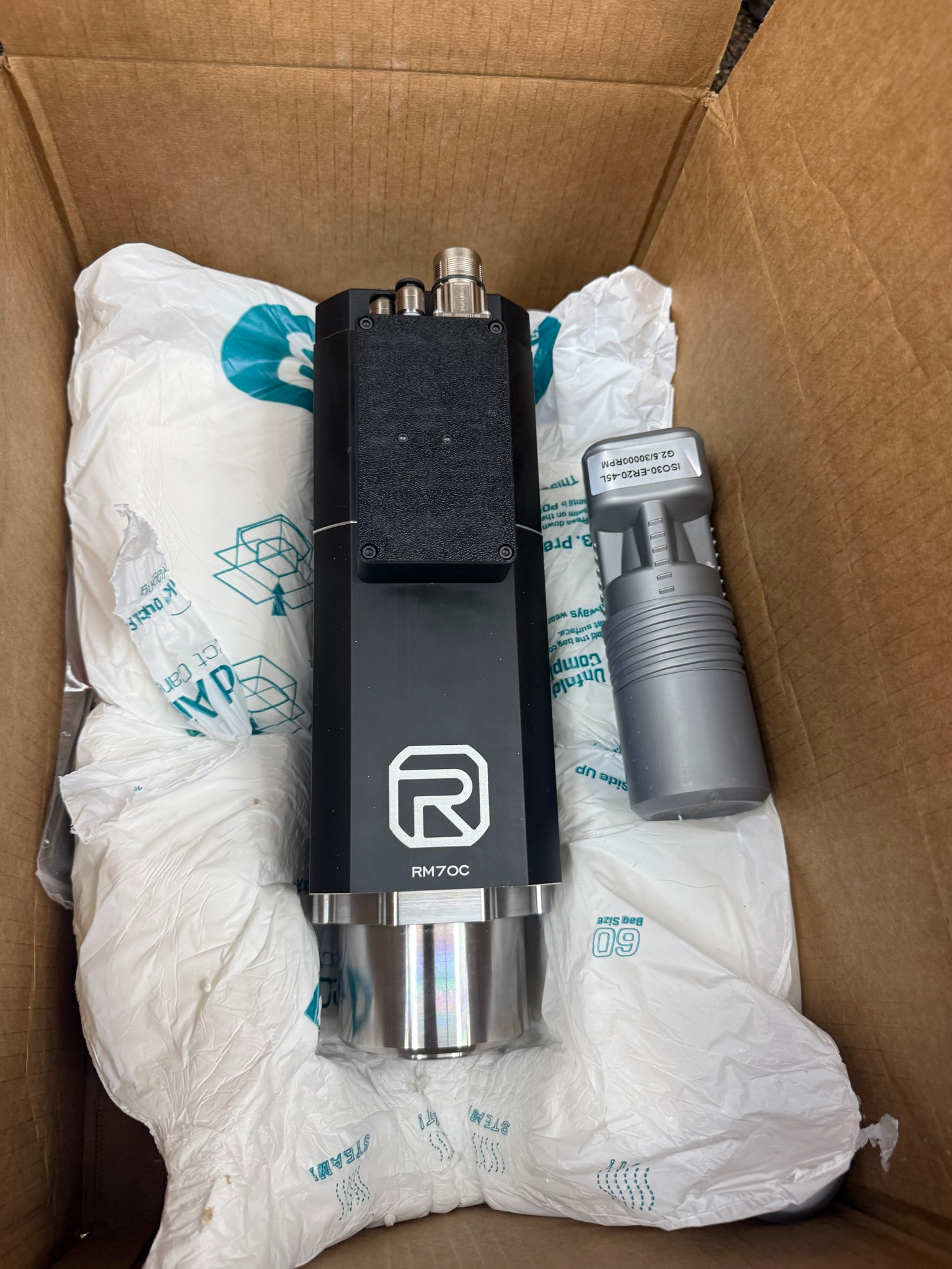
Does anyone have the base spindle mount plate drawn out? The first plate that connects to the lead screw and linear rails? I got an RM70 spindle from CNC Depot and don’t want a bunch of added stick-out.
@amosdudley has a nice CAD drawing of most of the machine, including that plate, in OnShape. I’ll let him respond with details.
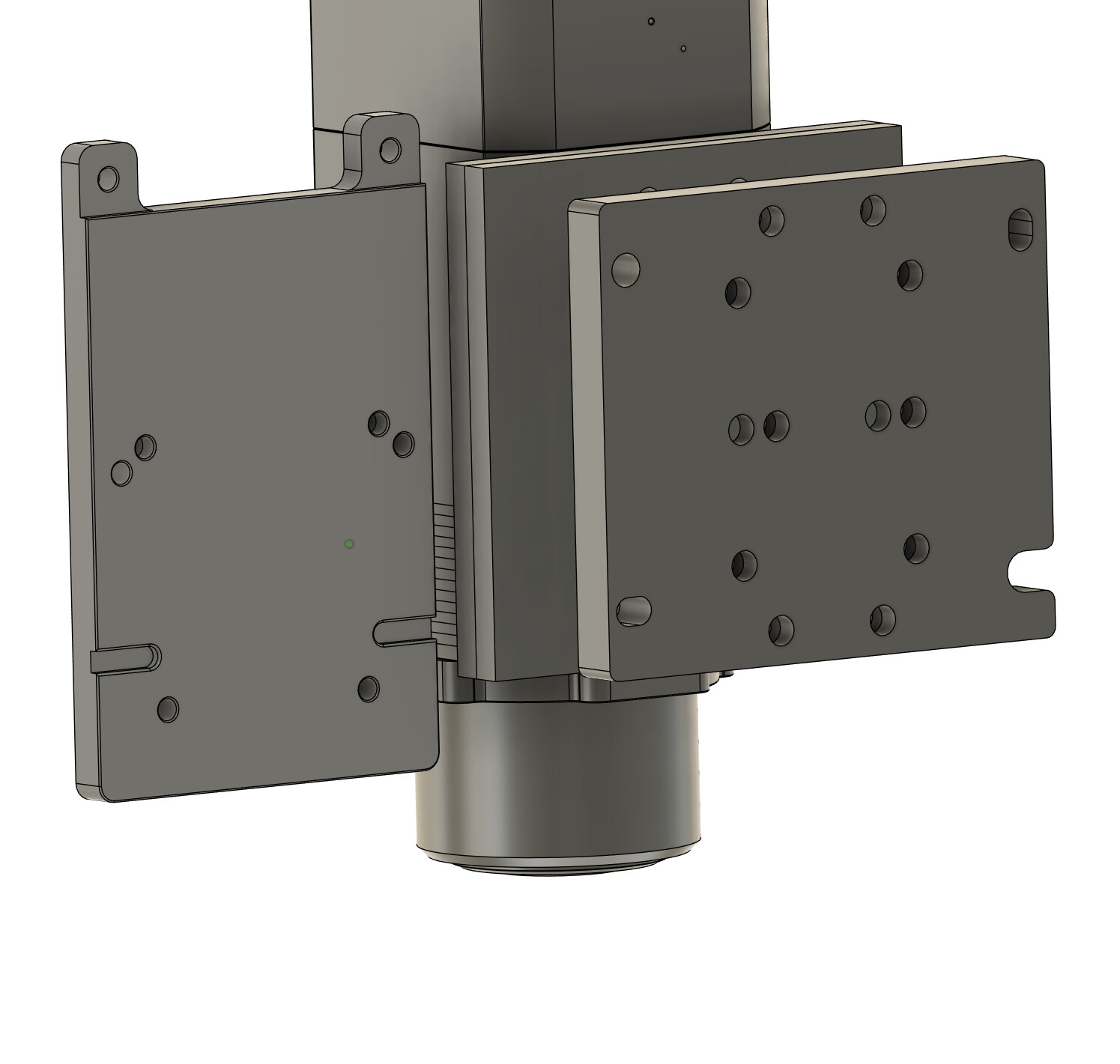
For that rear mount spindle I think you’ll need some sort of adapter plate, since it is bolted onto it’s plate from behind, and the bearing blocks on the MR1 need bolts going in the other direction. You’ll need two plates connected to each other on the perimeter to solve this.
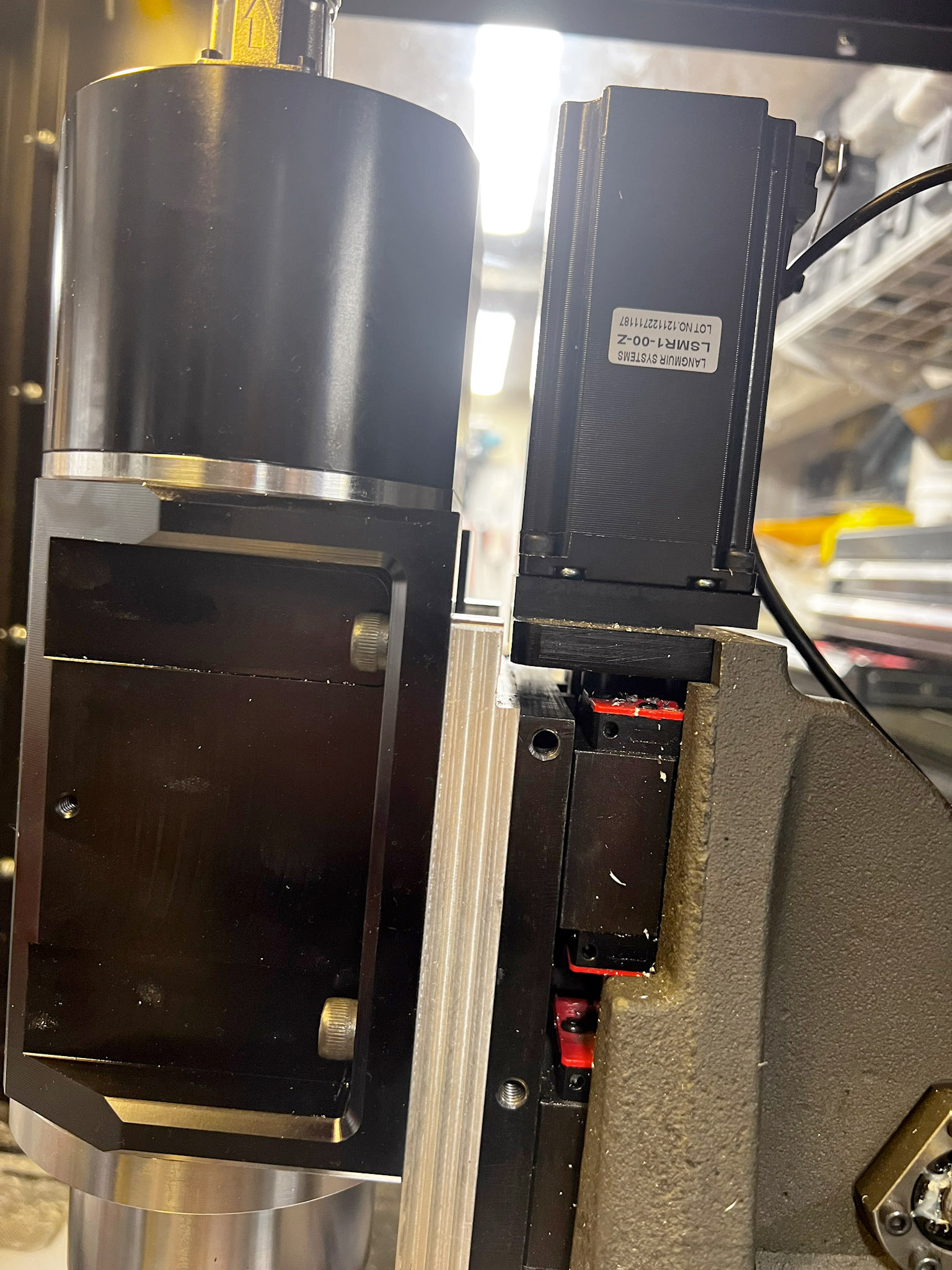
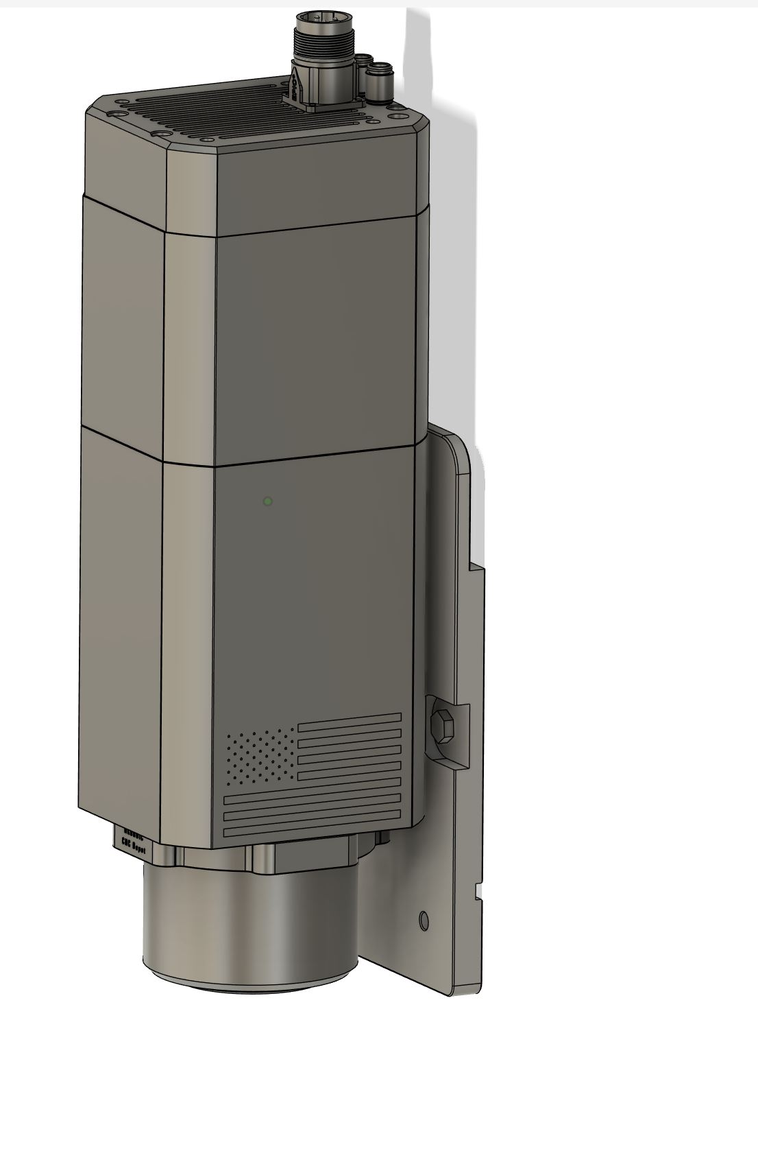
I also had interference problems with my FM30F unless it was spaced out slightly. Enough of my machine is changed that I can’t remember exactly what it was, but I think that the silver top of the CNCDepot spindle might have run into the adapter plate that holds the Z stepper.
I haven’t seen the RM70 before, that looks nice. Do you have a torque curve for it? I wonder how lower end torque compares to the FM30F that I’m using. Obviously high speed torque should be much higher.
This photo shows where the interference would be. You need at least some spacing away to avoid hitting the Z stepper. The silver plate there is my original adapter made of aluminum, I eventually made a replacement out of steel.
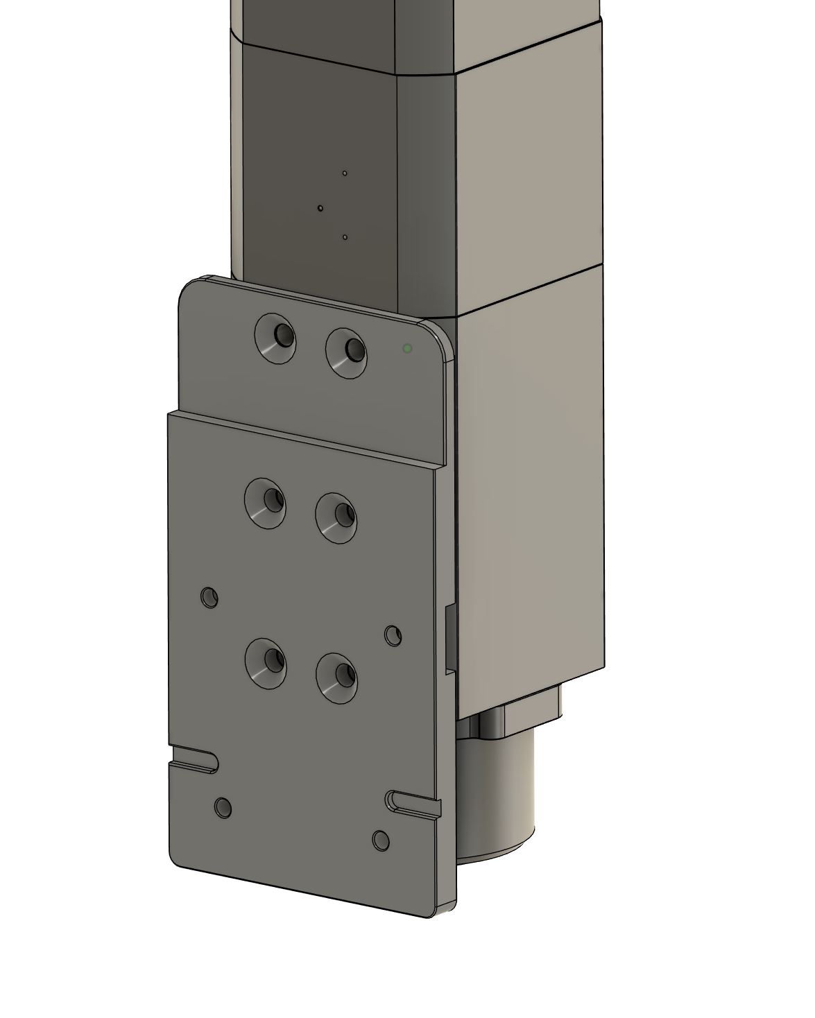
I have some 12mm steel ground plate, I was going to use to make the adapter. If I kept the original plate in place, my guess I would be around 36mm out from rails on ground plate on back of spindle. Thanks for that side photo;![]() Here is the avid motor specs same motor as cnc depot :
Here is the avid motor specs same motor as cnc depot :
av70s_spindle_specs.pdf (149.9 KB)
Thanks for sharing the spindle torque curve. It’s very similar torque to the FM30F below 8000rpm, but being a 2 pole motor lets you get to 24K RPM which will help on aluminum and wood.
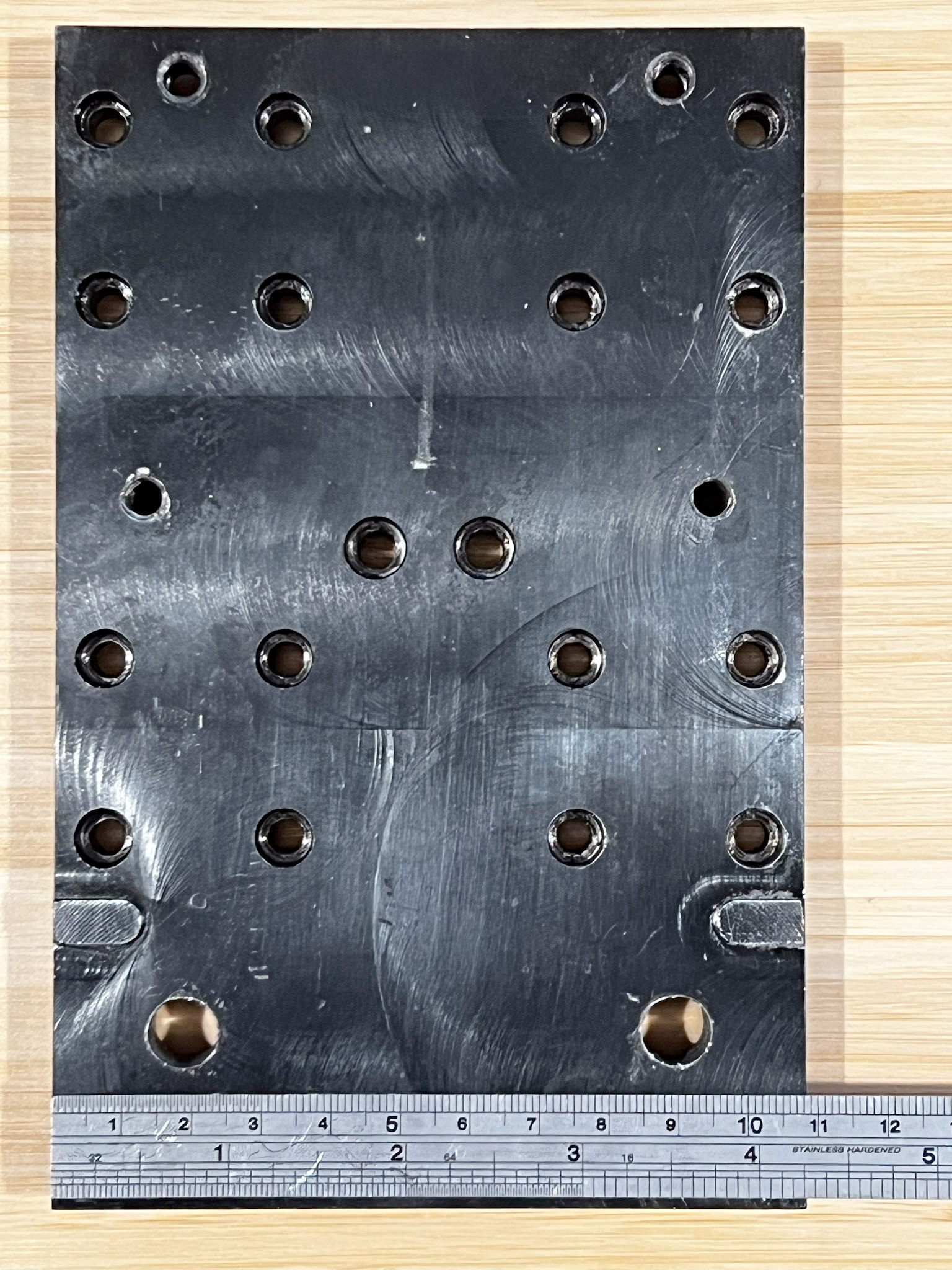
The plate in that photo is 16mm, and Langmuir’s plate is about 10mm (probably 3/8” given their love of imperial measurements). I hear what you are saying, but you’ll need to figure out how you’ll do the mounting and how to avoid interference. The top mounting bolts are slightly higher on the RM spindles than the FM spindles, making stepper interference more of an issue.
I guess I have nothing to gain by redoing that first plate. Did end up using languirs location notches or avids traiming plate designs : I have both uploaded to fusion
I figured it had near langmuir stock spindle midrange torque all the up too 18k.
It’ll still have less than Langmuir torque at lower RPMs. This is mainly a concern when drilling with HSS or cobalt drills, where you need lower speeds. I don’t drill holes over about 3/16” anymore and just interpolate, it works well. I have a couple of carbide drills to play with as well.
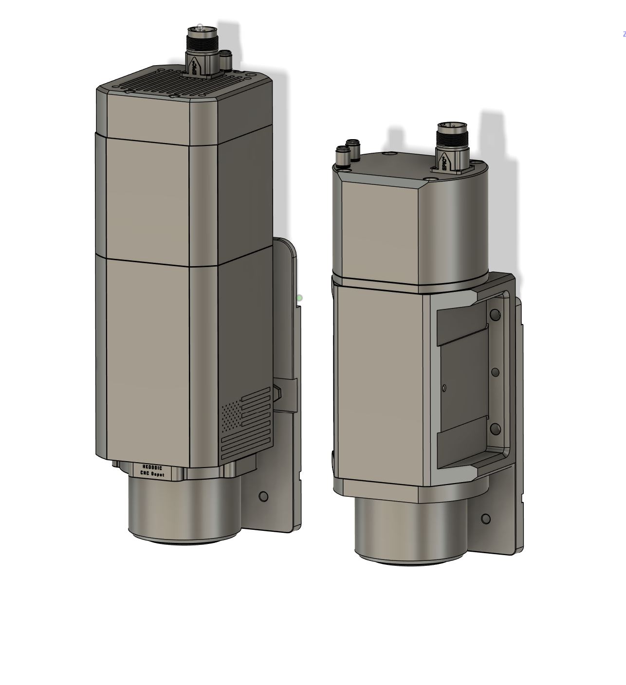
I like the Avid design, but to make it work you need to make both plates, and at the time of my conversion I didn’t have a 3D scanner. Now that I do have one I would be tempted to make a very good model of Langmuir’s plate and make a replacement that has the back of Langmuir’s plate and the front of Avid’s, and then you could use Avid’s tramming design. I didn’t want to stack up 3 plates.
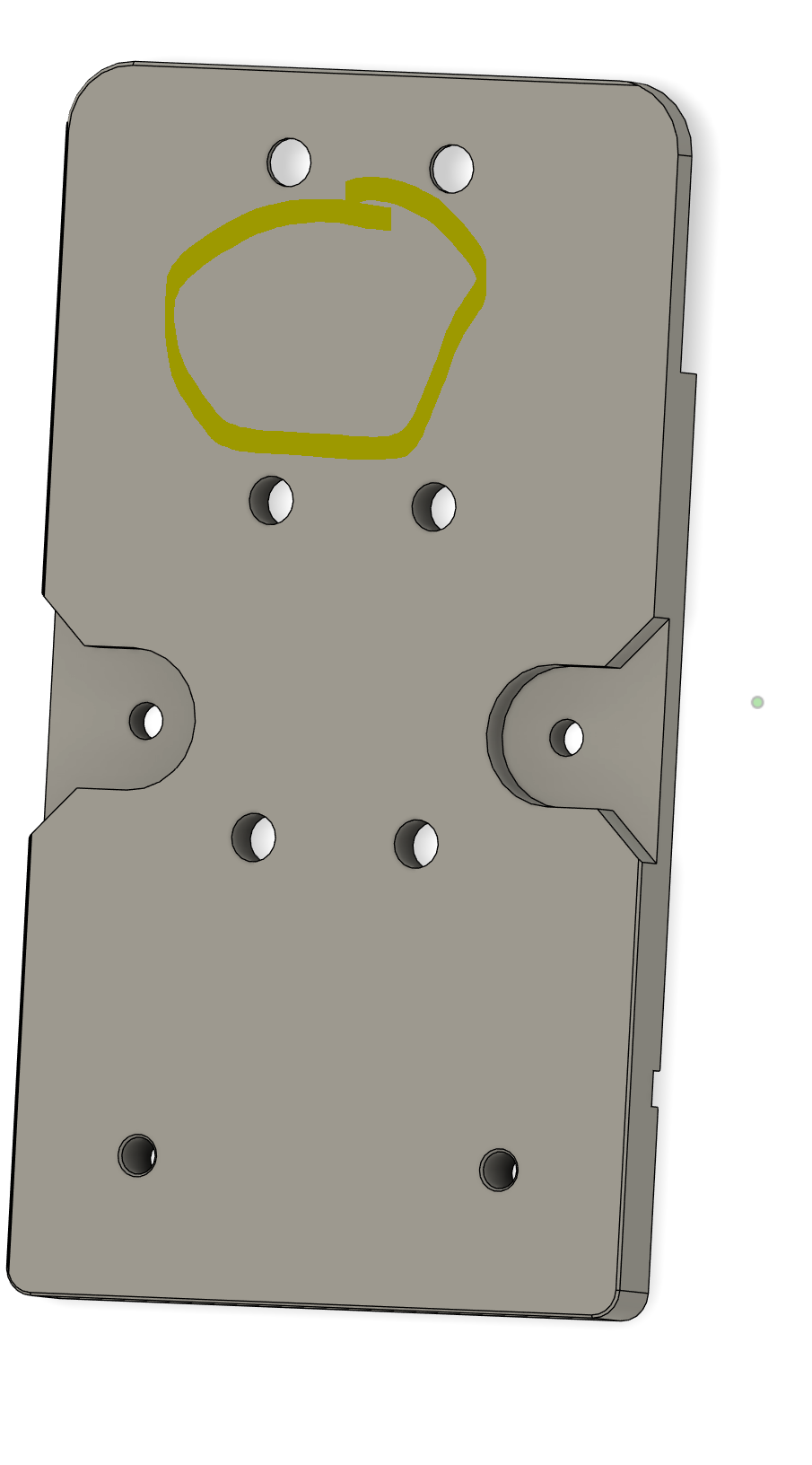
Langmuir could do it’s users a service by publishing the 3D model of that plate specifically.
I think I might be able to mount it with a single plate. Did you end up with any tilt or nod issues after mounting yours. I wonder if i need to bother with the tilt adjustment?
That’s basically what I made. I consider that two plates, you are mounting a new plate to the plate that the MR-1 has.
The MR-1 plate doesn’t have mounting holes up top, but there is plenty of meat for them. I made my own (using a hand-drill and tap since I didn’t have a drill press or manual mill at the time). Otherwise your plate is basically all supported from the bottom.
How do you plan on getting to the bolts to mount your plate to the MR-1 plate once the motor is already attached to your plate? Are you sliding nuts in from the side and turning them an 1/8 turn at a time? That sounds painful…
I could chamfer the inlet and get a little more movement for the second set of bolts like this: Did you go with one bolt in the top like yellow circle ? or how did you avoid the rail cars?