ATC for the MR-1?

Langmuir does have more collet nuts. I bought a half dozen from them back at the end of June. Basically I have the most common collets already in nuts that I have been using along with a dedicated collet and nut on the touch probe. Make tool change pretty quick.
Has for atc. I think the current spindle could be redesigned to have a power draw bar to use quick change collets and still use the current servo drive.

I think this is one of the simplest rack style atc I have found but still can see the level of struggle the op went through to get it to work.
While I would love an atc, I do understand that the amount of engineering need from Langmuir would be significant and would rather seen them focus of cut control improvement and 4th axis before atc since I can see those has being a more manageable task that has a quicker increased benefits

2 Likes

Yes I’m aware collet nuts are available. Even if the MR-1 24mm collets nuts are reasonably priced there are aftermarket specialty nuts that won’t fit.

A MUST HAVE for Anyone using ER Collets, Get a BEARING Nut and here is WHY.

Read about these on ClockCNC. Easy Zero Nut.

I think the spindle could be sleeved and re-threaded for 25mm collets.

The problem I’m seeing with the rack style holders or any ATC designed to be fed from the rear of the machine, is they have to clear the carriage which is fixed at 5-1/2”.

A low profile ISO20 tool holder is 3-1/4” from collet to pull stud. A low pro ISO/BT30 holder is 4-3/4”. So the gantry needs to be raised significantly for the 30 tapers or your tool bit lengths when using an ATC will be limited to 3/4”.

1 Like

Not a problem with HSK25 holders

I’m glad BrianS brought this up! I’d been thinking of raising my gantry by 1 inch, but don’t really want to go higher than that. In measuring everything else I hadn’t really considered tool holder length.

The hard part with HSK25 (or ISO20) is finding a good spindle. Do you have any recommendations?

I went and measured the machine and thought about this some more.

The real issue is the height of the lower Z axis, which is 5.5" above the table as @BrianS said. This is 3" deep front to back. The spindle itself can be installed to have the ER collet sit in exactly the same place as the stock MR-1 spindle.

It’s not ideal, but one solution is to run two racks of tools, one on each side of the machine. With slightly over 3" spacing each of these could hold at least 5 tools (probably 6) for a total of 10-12 tools. Obviously I’d be giving up X space, but the machine has ample X space so that isn’t a huge deal (at least for my needs). Keeping chips off of the taper will be a challenge on it’s own.

A one inch riser also gets maximum tool stickout to close to 2" using the shortest toolholders, which is totally reasonable.

If planning ahead someone could make a narrow trough for the tools in the concrete – but my concrete is already poured and I don’t really want to go making holes in it.

I’m going to stew on it for a few days.

The Mechatron one is the only one I know of. Yes, it’s pricey. Decent weight reduction though, given that the current spindle + servomotor + pulley weigh something like 32 lbs.

Stock spindle, motor, and belt is 37lbs on my scale. Plus a little extra for the shroud (which I didn’t weigh). So most alternatives will end up being lighter.

Torque on the mechatron ATC-8022-30-HSK25 is awfully low at under 1nm. Are you thinking of another model?

Spinogy X22 is the best HSK25 option that I’ve seen, but ends up at over $6k. They offer it with a 4 pole motor which gets about double the torque. You can also get a 3kw motor for even more power.

Oh yea, that looks way better at a glance.

Didn’t you raise yours an inch already and was planning to raise the y rail plates as well?

Thinking about this some more. Yes you can gain 1-1/8” to 1-1/4” by moving to outside the carriage but you wouldn’t need 2 racks. Just move the carriage all the way to left or right before moving the rack into position. The tool setter takes up some X space already. Yeah, I would guess the same after taking measurements…15-3/4” or room for 5 or 6 tool holders.

The other issue is keeping tool holder shanks away from chips. A rack sitting at the table level will need the additional height of a cover to block chips. But what if a rack could swing and lift the tool holders up and out of the way, similar to a one piece garage door opening, ending with them 5-6” off the table and the tool bits pointing toward the rear of the machine? A mechanism could be attached directly to the gantry in places where the bearing slides wouldn’t interfere.

Don’t get me wrong, the HSK tooling is very cool and all…it’s just hard to justify the cost of that tech for a hobbyist.

I ordered the CNCDepot spindle this week. I’m as excited about 16k rpm as the ATC aspects, and will probably use it as a quick change system first with a manual tool release button. Both tool height and keeping chips off won’t be an issue with quick change. It will be a lot faster and easier than the silly ER20 collet on the stock spindle.

I need to go shopping for pneumatic parts next, make the adapter plate to mount to Z, and start planning for the rest of the install.

CNCDepot released a bunch of new spindles yesterday, but the 2.2lbs/3hp is still probably the right choice, especially since they don’t have 4 pole motors in the bigger 4.0 and 5.0 HP sizes.

2 Likes

How about an imported 5.5Kw ATC for $1300?


Also comes in 4 pole but no 220V line drawn.

Saw a 3Kw version for about $800.

I was happy paying a premium for US source, manufacturer, and support personally. AliExpress has lots of options like that with limited specs that I didn’t want to take a chance on.

It would be great if someone else finds and documents a good import option. I looked at the better known brands but ruled out random AliExpress ones.

2 Likes

This new video shows how terrible the runout on the $250 BT30 spindles can be:

Now those are obviously a lot cheaper than the $1000 import BT30 spindles, but I am also weary of those when I can’t get service.

I got a couple of ISO30 tool holders to play with while I wait for my spindle. I’m standing them up on 1/2/3 blocks to show height with a 2 tool stickout. The 5.5" height clearance isn’t a big issue really, the height that matters is the distance under the gantry which is more like 7 inches. If I’m willing to give up 2 inches of Y I can put the tool rack along the back edge of the table along with the tool setter, and allow the gantry to pass this area over the tool setter. Here is a photo showing how that works:

This gives just under 16" across X for tools, which I think will allow me to have room for 6 of them.

Another option is to put them across the front of the machine, ahead of the table. I think that will allow for 7 or 8 tool holders to fit. Here is an example of that, and you can see that the tool rack would mostly be over the epoxy (losing minimal Y). The nice thing about this solution is that it would be easy to change tools, the downside is that it would reduce access to the vise because I’d have to reach over the tools.

I’ve been measuring the Z axis plate while waiting for my spindle. I was torn between making a new plate or making an adapter that bolts to the existing plate and which has mounts for the new spindle. I’m going to do the latter for now, with the downside that this will offset the motor by about the thickness of the adapter plate (at least 1/2"). Someday down the line I’ll make a single piece replacement, but this will also require making adjustments to the Z stepper mount to get the required clearance.

1 Like

I didn’t need to see a video to know that spindle was a piece of junk. I came across them 3 months ago and read the Q & A. There’s good reason why I didn’t share a link until now.

https://www.aliexpress.us/item/3256805422237158.html?spm=a2g0o.productlist#nav-specification

Q: What is the top speed? How much power?

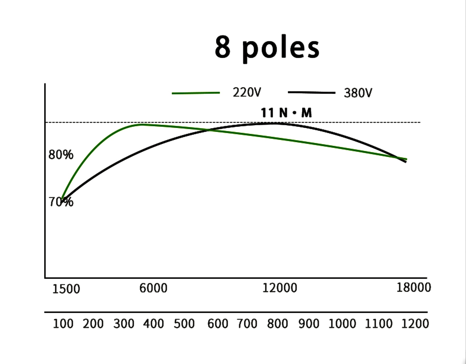
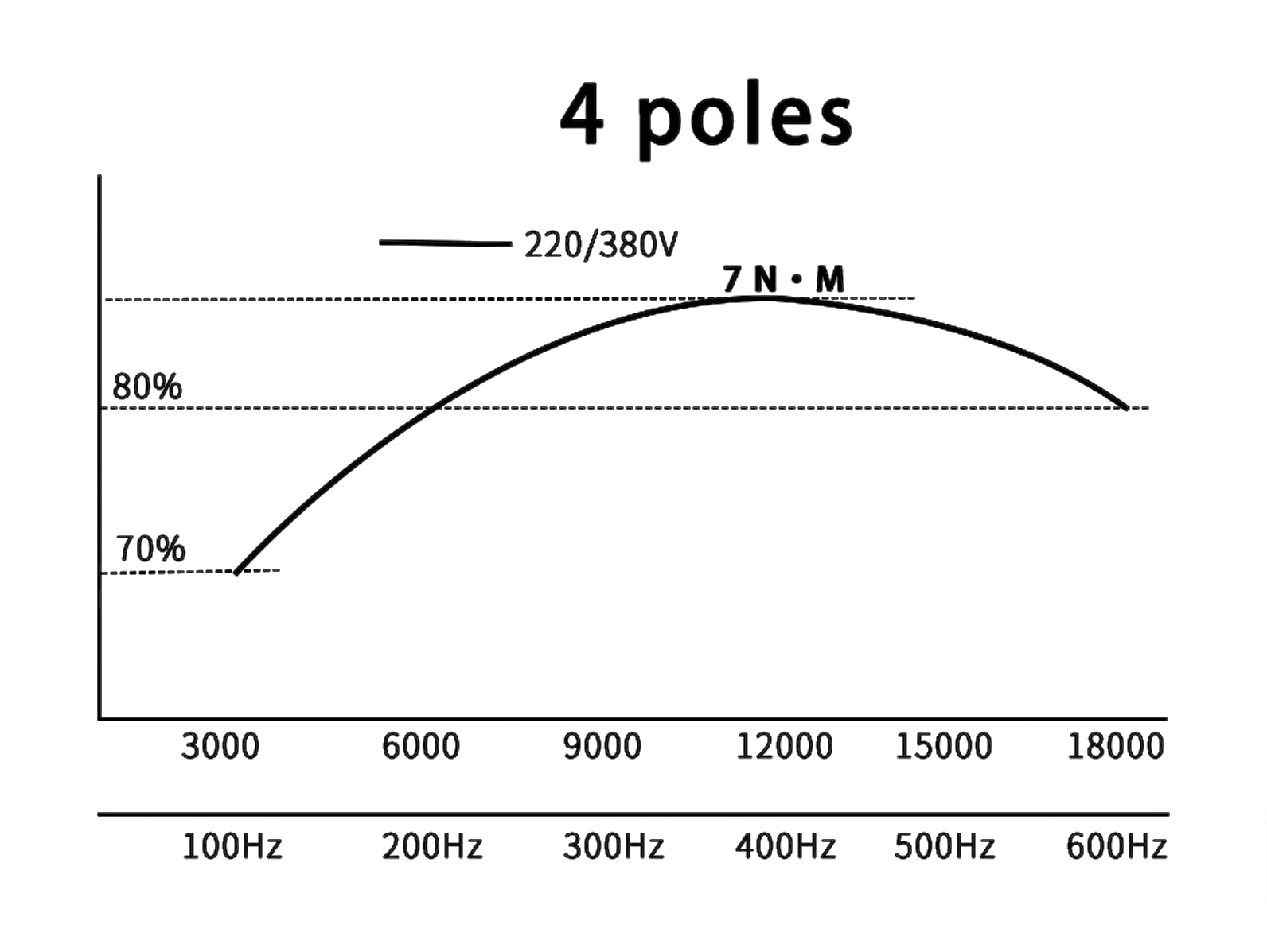
A: 5000rpm, this product is a non-powered tool change spindle without a motor, so the power is determined according to the motor you have equipped.

Q: What kind of bearings are used? What is the number of bearings?

A; 5 deep groove ball bearings are used.

Q: Cylinder model? How much pulling force?

A: ROANY SDA 80*10, 0.8 air pressure, broaching force is 300 kg.

Q: How about the machining accuracy?

A: The shaft is heat-treated with ultra-high hardness and fully ground, and the inner taper runout of the main shaft is 0.02~0.05mm. Under normal circumstances, 0.02mm, perfectionists place orders cautiously, after all, the price is already very low.

Q: What type of handle is used? Handle stud model?

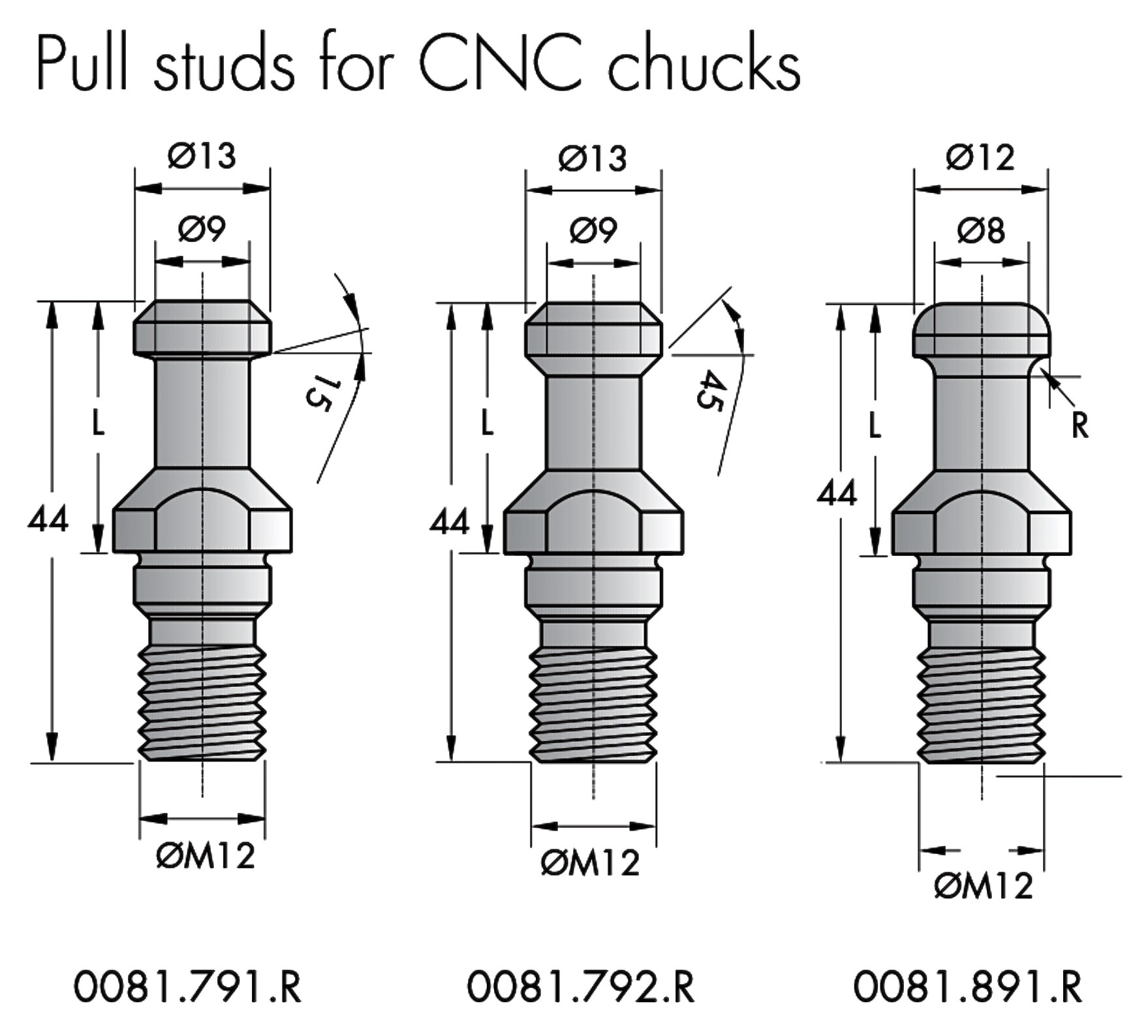
A: BT30ER20 tool holder, without ER collet, pull stud model BT30-45°.

———————————————————————————

No clue as to how powerful of a motor it can handle. Deep groove bearings (not angular contact) of unknown material, tolerance, and size with 5K top speed. Taper runout stated 20-50 microns, so what did he expect? Pull force Q wasn’t answered but based on the spring stack it’s probably the same or less than the Samurai 120 which is #225 I think.

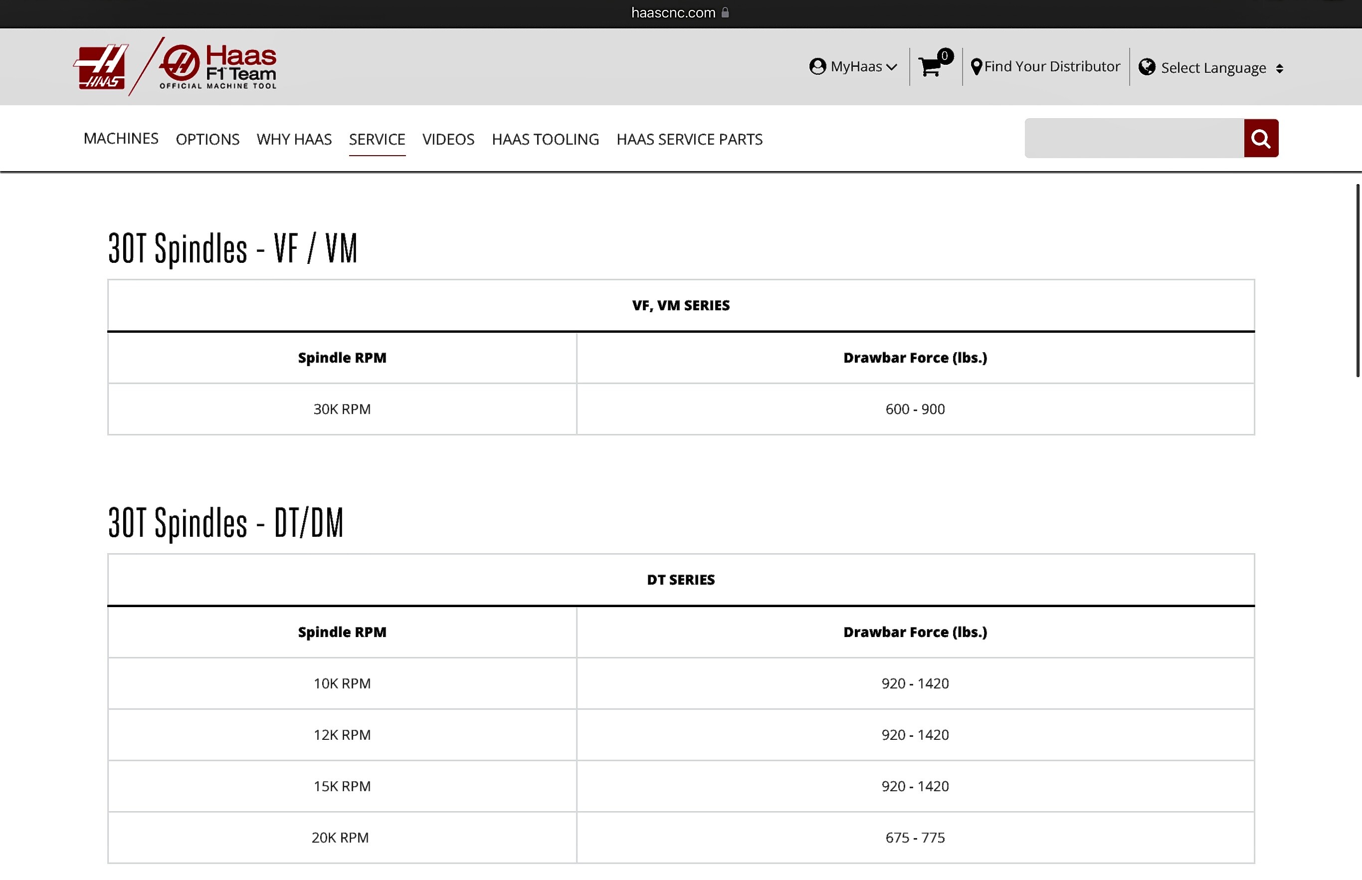
A 30 taper needs #920-1420.

The problem with these much higher spring rates is you would destroy the spindle bearings using a pneumatic cylinder to compress them. You need something similar to a floating piston caliper used for car brake rotors to compress from both ends of the springs so you don’t transmit excessive loads to the shaft. Which is how Tormach does it and they use (16) 40mm dia. Belleville washers to get adequate drawbar force.

That poor guy in the video has no idea how to grind a taper but even if he sent it to the same guys GlockCNC uses and gets a $900 secondary grind “for 0.0001 TIR or less”, the spindle bearing tolerances simply aren’t there to make that happen.

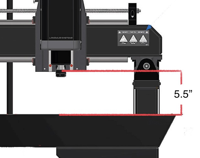
If I were to guess which spindle, you probably ordered the FM with the wider mounting flange. The MR-1 plate was a pain to remove. All the screws were excessively torqued to the point where I thought the Allen wrench or the screw would snap off before they broke free. Finally got it all apart and can send images of both sides of the plate if it would be any help.

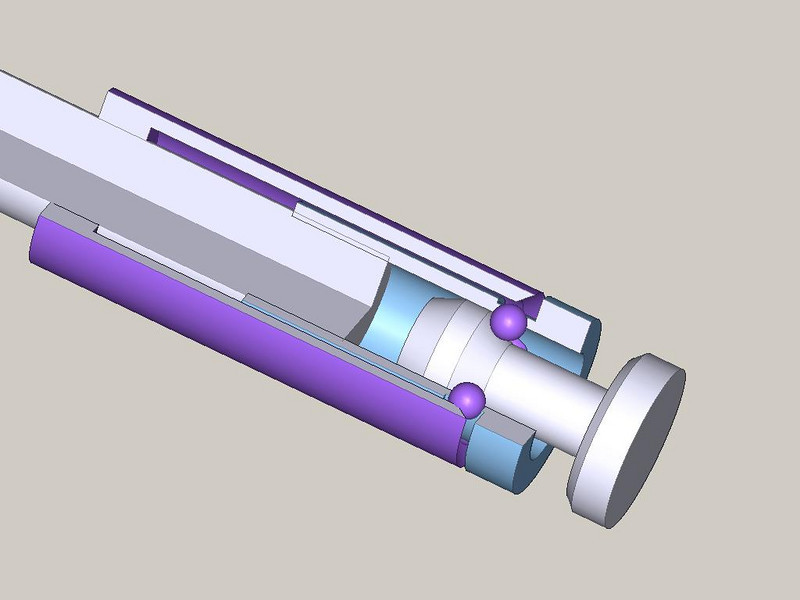
Also if the ISO tool holder is from Amazon like mine, it probably has the pull stud with a 3mm radius. They have to be compatible with the spindle’s stud puller whether it’s a 15/45/90 degree gripper or the ball type.

When designing a rack, are you considering one that is fixed or something that will move into place. We’ve seen examples of both in this thread.

That wasn’t the case on my Z plate. I pulled it off no problem yesterday and took some basic measurements. I had limited time and didn’t take good measurements of the back – if you have those drawn already I’d happily take your drawing.

For now I’m just going to make an adapter plate that mounts to the existing Z plate using the MR-1 mounting pattern, but with two additional threaded holes at the top that I can add. This is easier because I can add in the 3mm clearance to clear the stepper motor holder and get the height that I need. The top mounting bolts on the FM spindle are about 1.5cm above the top of the MR-1 Z plate.

It’s tempting to do the moving kind because there is a lot of space behind the table on the machine. That would also give me room to make a chip cover to keep the tools clean. It’s a lot less work to do the fixed time, so I’m sure I’ll start there.

I’m not in a major rush to do the full ATC, just doing quick change tooling is a good starting point for me. That will give me time to experiment and figure out how I want to do the tool changer.

CNCDepot spindles use the concave radius style of pull stud, and that’s what my sample ones came with.

2 Likes

Consider yourself lucky. I had to add a vice grip to the Allen wrenches for better leverage and often heard a loud “kink” as they broke loose sounding much like metal breaking. I twisted an inexpensive wrench the first time I tried to loosen the pulley bolt.

Nothing has been drawn unfortunately, I was just offering a snapshot with a few measurements.

Looking over the plate, 2 additional bolts near the top would distribute the load much better. MR-1 uses (2) 1/4-20 bolts…plate thickness is sufficient for 5/16” or M8 bolts. Had their Z plate been about 3/8” wider and an inch taller you might have gotten away without an adapter.

I purchased some 20mm rails to replace the 15mm ones provided…that requires some modifications to the carriage and an entirely new Z plate. I figured out a way to simplify tramming but it will require some Z plate & spindle housing mods, and an additional intermediate plate.

All the commercial spindles I’ve seen use the gripper style puller. If they make a gripper for the radius style stud I haven’t come across one yet. The ball stud pullers look a lot easier for a DIYer like myself to make.

AvidCNC has a nice tramming plate setup that would be easy to copy:
https://www.avidcnc.com/3-hp-4-hp-spindle-tramming-mount-p-360.html

I was going to do that, but am going to try something easier first (closer to the set screw mod that is popular on the MR-1).

1 Like

The set screw mod is fine. What concerns me are the two small notches used to align the spindle housing with the Z plate. If there isn’t enough play in the notches it could be fighting against the set screws.

The AvidCNC plates look like they would space the spindle housing out at least 1/2”….or more than recommended by LS. If machined properly my plate would only add 1/8” or less and wouldn’t require any new fasteners. I’d still recommend replacing the spindle housing 1/4-20 screws with 5/16” since the button heads have very little contact area.

I had to relieve mine a little to get in trammed after the set screw mod. no big deal.

The notches won’t be a problem with my setup because I can machine a larger groove on my new Z plate. I also moved away from the Avid system because of the second plate. You could do it with a single plate if you modified or replaced the existing Z plate.