I don’t know if this is a Langmuir issue, an F360 issue, or a little of both. This part is fairly small - 3" from wingtip to wingtip. I’ve included all the inner spaces using closed loops. The lead-in is set to 0.1" and I’ve tried different lead-in angles. The simulation shows me that only the outside of the shape will cut. I also tried setting the profile using Face Contour. That will include the upper right space above the propeller, but not the others.
Look at your lead in/out compared to areas you plan on cutting. You might as well do 0 lead in/out and 0 pierce clearance. It’s really small and might not make it.
Could just set really small lead in and out but that tiny triangle is going to be tough. Going to end up being a dot.
1 Like
This did make me laugh ![]() . Never the user issue. Sorry my humor but I do see your new and this is tough one since it’s really small. Very cool project so good luck and post pics when you finish.
. Never the user issue. Sorry my humor but I do see your new and this is tough one since it’s really small. Very cool project so good luck and post pics when you finish.
1 Like
I did not mean to imply Langmuir or Autodesk is to blame. I assumed people would know I meant I was doing something wrong with F360.
2 Likes
I completely understand…no worries
See if this solves your issue and repost if it don’t. GL
From your screen shot, your lead-in / out is closer to .2, not the .1 stated. I would check the Pierce Clearance setting. (Last tab on your cutting op.) Set it to 0. (Pierce Clearance adds to the lead-in / out length.)
Additionally, what is your kerf set at? Has it been measured? If the kerf is larger than the detail openings, the path will not follow the profile correctly. Possible solutions - lower amperage consumables for a smaller kerf or scale the design up to allow the details to be cut.
1 Like
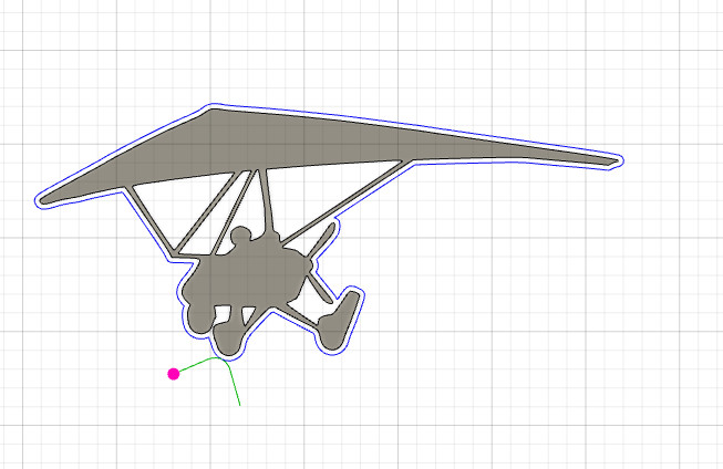
In your attached screenshot, the pink circle represents the kerf width setting, and the green line represents the lead-in / lead-out setting. In order for a contour loop to be included in the toolpath, both the kerf width and lead-in / lead-out must fit within the ‘dead space’ on the inside of the contour loop. If the kerf width or lead-in / lead-out do not fit, then the contour loop will be excluded from the toolpath.
You can try selecting a different entry point or modifying your lead-in / lead-out settings in order to force them to fit inside of the interior contour loops, but the space shown here might be too tight to fit what you are trying to achieve due to the overall size of the piece. This can be seen at on the perimeter contour loop as well, as it appears the kerf width does not fit in the gap between the propellor and the landing gear.
1 Like
Try this version. I opened up a few areas. It is about 5.5" from wing tip to wing tip, so you’ll need to scale it back a little if you need the original 3". However, the changes I made at least will help if you do scale it.
I was able to generate a toolpath with this dxf.
Glider.dxf (50.3 KB)
Edit:
With a few more small changes, this one generated a Toolpath (Kerf = .04") with 3.3" wing tip to wing tip.
Glider 1.dxf (49.0 KB)
1 Like