Sorry adding another video but this one is our brother company now…4th Axis CNC Plasma Pipe Cutting Tiki Torches - YouTube
No clue on cost but sure is cool
Sorry adding another video but this one is our brother company now…4th Axis CNC Plasma Pipe Cutting Tiki Torches - YouTube
No clue on cost but sure is cool
If you have to ask, you can’t afford it.
Very cool indeed. if we can get something like that going, it would open up huge opportunities for the sign and craft makers here.
I am hoping that Langmuir will have this out for the XR, or I will be spending $22000. for the bend-tech dragon A250 tube notching machine.
Arclight has one, and Premeir plasma, both under $2k for the addon for their tables - which are double the Crossfire.
Hopefully Langmuir comes out with a maker add on for their line of tables and keep it right about $1k. You can DIY one for significantly less. $25 for the stepper motor, $100 for a 4" 3 jaw chuck, another $150 in misc hardware, bearings and some plate.
One of us is going to crack the code and procedure to this and hopefully make it open source.
Between the Adrino, RC cars, CNC anything that the individual can get parts and education pretty easily, I give it another month and we will have a decent DIY system in place.
I did hear them (shop sabre Vid) mention gantry height. Wonder what the max would be on the XR due to gantry height?
Just because you can afford it does not mean you can justify it. Big difference!
You always have to remember ROI
Currently allow GF to get 3 items off the dollar menu but if one does come out anytime soon I guess it’ll only be 2 items…everyone will sacrifice to find the extra $$$. Lol
Oh, come on guys, what’s another 100 hours of overtime among friends?
Can’t wait to see what you came up with. I have some questions on how you got the pipe to spin and calculating steps and drivers and pulleys. Its giving me a headache lol.
Where did you get this information from? If true, then i would have to have pulley system of 2:1?
The lead screws on the Pro are 3/8-8 4 start and 1/2-10 5 start, which both result in 1/2" of travel per rotation.
Awesome info, thanks! The x axis driver is set to 3200 and y axis set to 6400 on the 2x2 table. Back to calculating what size pulley I would need with this new info
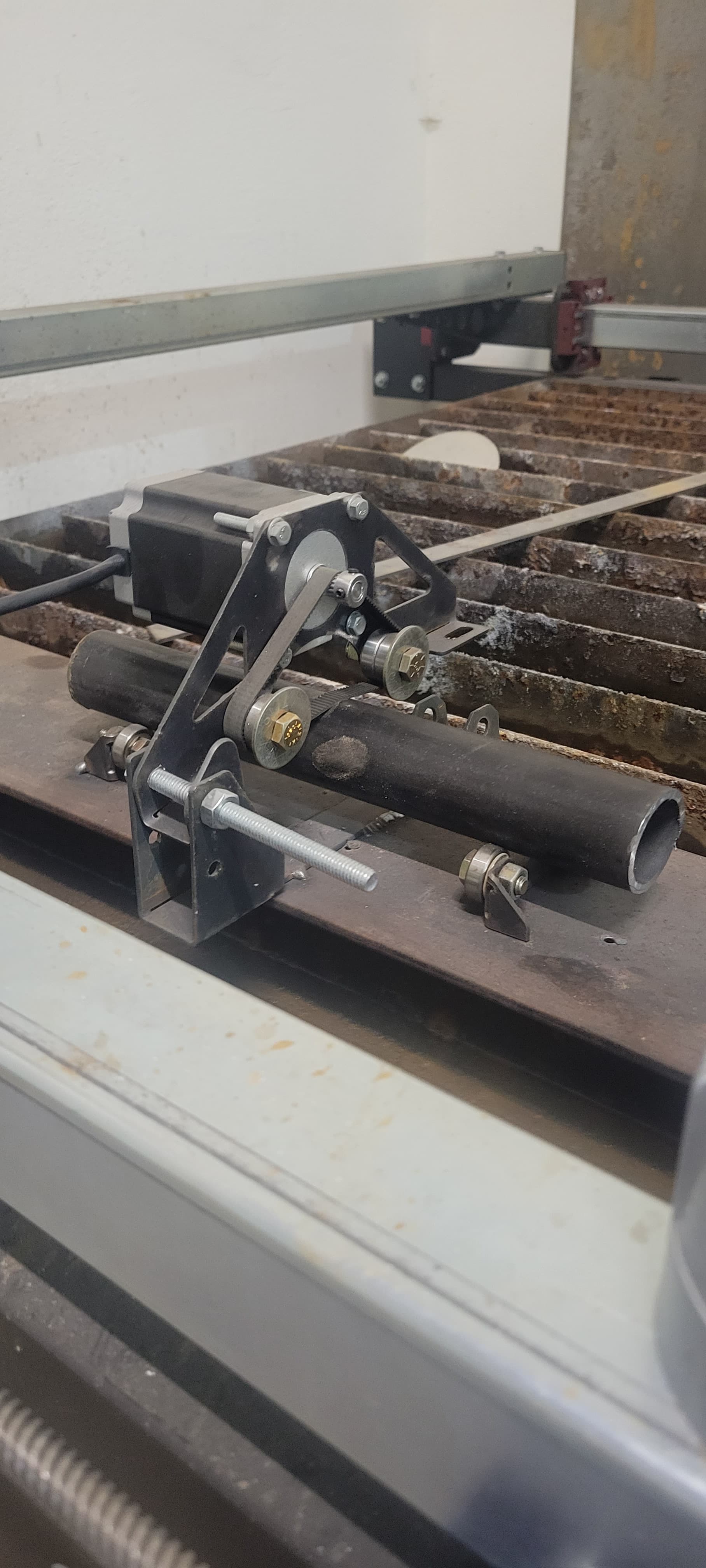
Some more info for those who want to do this, this is how i did it. I designed the rollers you see to use with skateboard bearings. That is welded to a scrap piece to keep everything square. I unplug the x axis and use that for the rotary. The stepper motor is geared as others have said so the rotation is off. The way i fixed this is when importing the bend tech wrappers to fusion to get my desired angle, I scale the x axis off the motor rotation to get the desired angle. Its not pretty, its not perfect, but it works for what i need. Sounds like several of you guys could improve on this design.
You have done a heck of a job with this, and thank you for taking the leap!
This is awesome! Could you give more detail and possible example of how you scale the drawing to match the rotation? Trial and error? Formula?
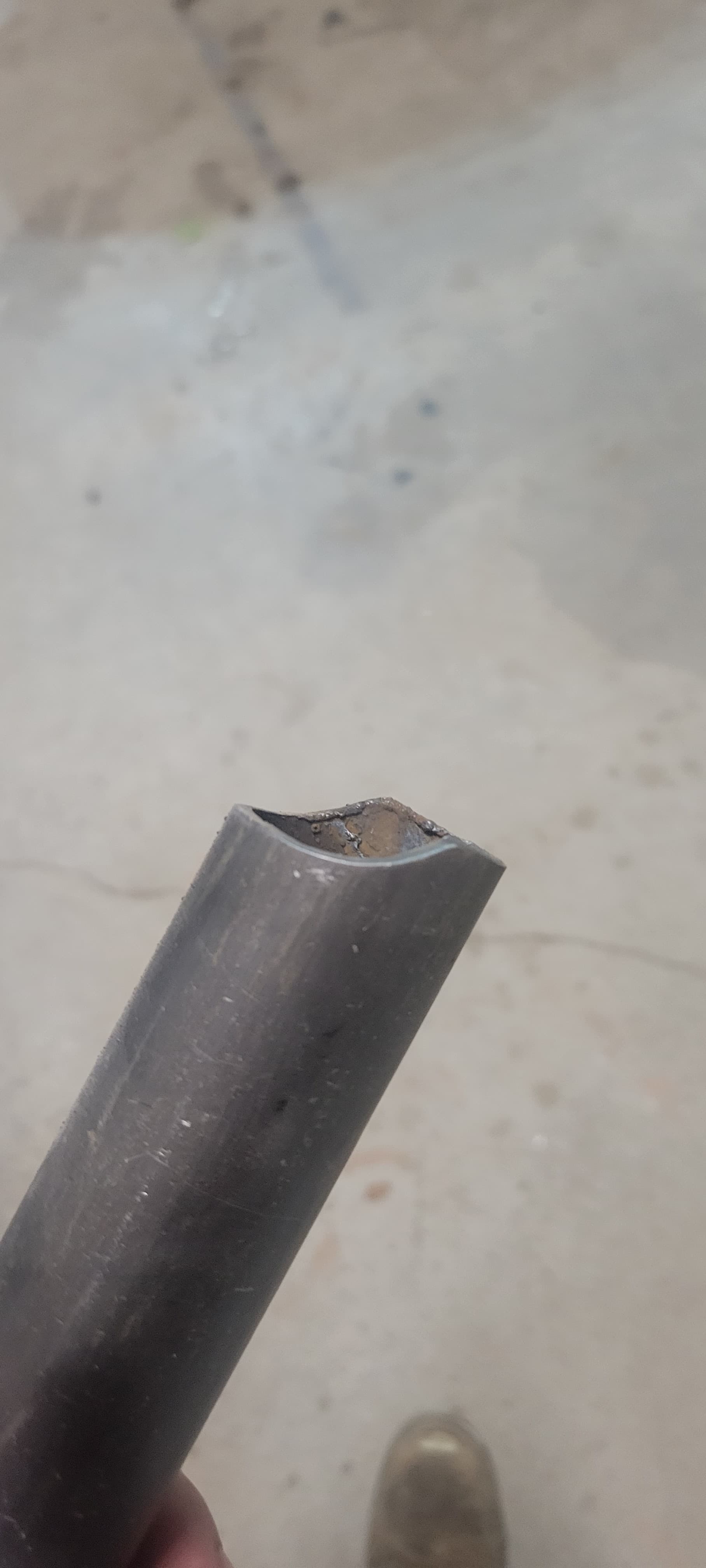
Lots and lots of trial and error and its still not perfect. When I first did this thread there seemed to be very little intrest in it and i couldnt find much info on it. I had to do the same 60 cuts repeated so i built this for that one task. If you are doing multiple different cuts this would be a pain in the butt. It seems like there is a lot of intrest in this now so i would love to revisit the topic and try to improve on it.
One of my original thoughts was to set the motor off further and run gears rather than the belt to match the x rotation speed, then maybe a belt off that. It definitely has limitations with the size tube you could do with the torch height with a setup like this.
I may have some free time this weekend and i can dig into this. Or if anyone has thoughts of how to build off my current design.
What diameter of pipe was it that you were cutting and how much did you need to scale the original drawing by. I feel there is a formula that could be calculated from this. As stated above the lead screws move a half an inch for one rotation of the stepper motor. So if a formula could be created and you just need to plug in the diameter of the pipe to calculate what you set the scale of the drawing every time. Might work ![]()
I’ve been thinking about this one for a while myself. I have been reading the thread and can’t get my head around why in this set up different size pipe would require different settings for the stepper. Isn’t that handled in the drawing of the cutline? If the stepper is turning at a constant mm per revolution then the variable is pipe circumference. if you use a software to figure the cutline like metalgeek.com you put the pipe diameter in there and it adjusts the length of the cut to suit. In another thread here @djlois shows how to reset the number of steps the controller thinks it takes the motor to move a given distance. To me it seems like that is the answer to the pipe diameter issue? What am I missing?
You are missing 2 x pi…as in 2 x pi x r which of course is the distance around a circle.
When notching some angled cope…you need the y axis to move too and you need y to move at specific x axis distance. So you need to scale x to match y (which Langmuir scaled for you).
So in theory you could scale that all in software FOR THE X ONLY, but the way I do it is much easier for me to keep track of especially since I build the whole tubing structure in fusion not just the copes.
Now if the software knows you have a rotary, it can send “X” distance in degrees and all will work after you scale it once, but I am not paying for that in fusion.
Hope that helps.
Hmmm I’m still not getting it, but not asking you to solve that for me! ![]() I understand the formula for circumference and I understand the concept that a cope consists of x and y movement. Where I am getting off track is that when you showed how to reset the distance moved per step on X that this was determined and adjusted for the difference between the drive system on the langmuir lead screw and the drive system on the rotary tubing cutter what ever that drive may be. I guess I have to build it and see. @Holdstronginc could you provide a few measurements or your drawings to save a few steps for the rest of us? Thanks all, great discussion!
I understand the formula for circumference and I understand the concept that a cope consists of x and y movement. Where I am getting off track is that when you showed how to reset the distance moved per step on X that this was determined and adjusted for the difference between the drive system on the langmuir lead screw and the drive system on the rotary tubing cutter what ever that drive may be. I guess I have to build it and see. @Holdstronginc could you provide a few measurements or your drawings to save a few steps for the rest of us? Thanks all, great discussion!