Pretty new to the table and think I’m starting to get the hang of it pretty well. I do a lot of work with tubing and was wondering if anyone has successfully added a rotary axis for tube notching. Ive seen quite a few other topics posted about it, but not sure if anyone has actually done it.
I could be completely wrong but my idea is unhook the x axis motor and use another motor for the rotary that would plug into the x axis. Ive seen a couple home made setups that use a 3 jaw clamp system and maybe use a belt off that to spin it. Hoping someone can give some advise here.
There is a guy on YouTube that made a copy of the Crossfire with 3d printed parts and a belt drive. He made a rotary tube notcher by doing exactly that. Plugging the rotary drive motor into the X axis driver. I think it’s JD’s Garage.
His version was easier, because he was using the same belt drive system on the rotary motor, so it moved the same distance per step. You’d have to figure out how to match the X axis step rotation on the Langmuir system.
Hi, did you get any further along? I also saw the video ds690 mentioned and am also just starting to draw the pieces needed. The stepper motor is where I know im going to have trouble getting it to match the spin speed correctly.
You will need to try to match the Nema 23 motor current type with what is on our tables - I think that there is only 2 available. The motors are pretty cheap so if you can’t get the specs on what is OEM, then trial and error.
Then a 1:1 drive to your indexer, either direct or same size shivs.
ETA - I just found the video. Smart guy he is.
So the Y axis motor, then a 10:1 drive system (I think I got that right) drive to match the table lead screw. Simple math could be done with the wrong motor to get the same rotation per step.
Somebody please keep this thread moving. I’m interested in this.
I would think that with a PRO table, that unless you wanted to pull the water table off every time you use this, that it would be easier to make a second torch mount on the back of the Z axis with a counter weight to keep it balanced, then run the rotary off the back of the table so the top of the pipe would be .250 above the slats.
Would also have to disable IHS and THC. Could get tricky incorporating both into a rear mount.
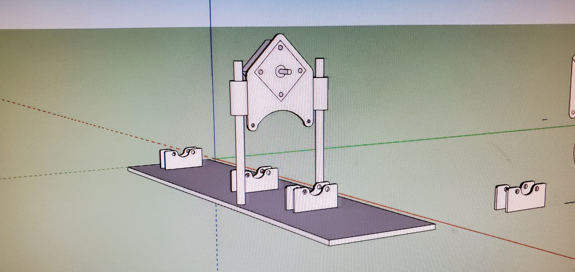
Im out of town at the moment and dont have a picture of the setup, but yes i got this to work. I will get a photo soon. I used some skateboard bearings as a craddle so the tube will spin with a nema 23 motor and a belt to spin the tube. I used my bend tech software to create the cut wrappers then transfered those to fusion and made the gcode. I then unplug the x axis and use that plug for the rotary motor and it works great.
So far I have come up with this stepper https://www.amazon.ca/gp/aw/d/B00PNEPF5I/ref=ox_sc_act_image_7?smid=AWQBCGWISS7BL&psc=1 . And if paired with this driver https://www.amazon.ca/gp/aw/d/B07S5XN5S4/ref=ox_sc_act_image_3?smid=A2ZDGCOOU4F0SF&psc=1 . You can set the driver to 1000 pulses and it will give you a 1:1 rotation to your CAD drawing. Then you would use a drive wheel and idler wheels that were all the same size and should be good to go. If you use the driver that comes with Langmuir’s setup you have to use different size pulleys to get it to spin 1:1. Now I truly have no clue if this will work I know nothing of this subject and used chatgpt to problem solve a solution. Please check this info and tell me if this would work.
The Firecontrol system is set up to convert 1 rotation of the stepper motor to 1/2" of travel. Whatever you do for your rotary system must also result in 1 rotation of the stepper being 1/2" of movement on the tube surface.
Think of the tube as a flat surface and the rotation is the X axis of that flat surface.
Was just thinking some more this morning. That stepper motor i mentioned has 1.8degree turn per pulse (from my understanding) so that would be 200 pulses for one full rotation. The driver inside the Langmuir system has a setting of 200pulses/rev. If set to 200 i could use a 5:1 pulley ratio to achieve the 1000 steps needed to make it a 1:1 spin or 1inch of cad drawing equals 1 inch of spin on the belt pulley. So confused lol. Got in contact with one of the guys that made a youtube video of his tube notcher (Dac Garage) and he doesnt have any of his old equipment or remembers much about what he used for parts. Did send me a cad drawing of his project though.
With merger I’m hoping that Langmuir comes up with 4th axis tube cutting for new XR. ShopSabre has tube cutting ability. I don’t have XR currently but this would definitely make me want one even more.
Unless I am missing something, you cannot get the existing drivers to match to the rotary speed UNLESS you only cut one size tube.
The reason being is the software doesn’t know about the rotary, it thinks it has to move one axis some distance. For example, you have a 100 mm tube and you want to cut it off, the software will tell the controller to move one axis 100 mm. The problem occurs when you change pipe size, if you want to cut off a 50mm tube, you would not want the axis to move 100 mm you want it to move 50.
And sure that would still cut it off square, but that is not the reason you are notching it. You need precision movement of two axes. Hope that makes sense.
It would be great if the software that we use could say, turn the rotary 10 degrees, but that isn’t the software most of us use.
I could be wrong and am willing to learn and to prove that I just learned that the plural of axis is axes.
It’s not a problem, if you design it to have the tube rotate on rollers. If the rollers move 1/2" for each rotation of the stepper, it doesn’t matter what size the tube is. If you’re trying to use a chuck to hold the tube, then that’s a different problem.
You do your cut file as a flat pattern, with the X axis being the distance of the rotation and the Y axis being the motion to make the notch or cope.
There are tube notching programs that will output a flat pattern of the notch.
Got it… I would be concerned about the consistent friction necessary on the rollers. On small pieces it likely isn’t an issue as it is just a notch, but I would think on longer pieces the piece would need consistent balance to maintain friction and/or some kind of rotary clamping mechanism.
I wonder if the drive were on the bottom rollers to take advantage of gravity for turning the tubing would be better. Less chance of binging on your rod approach, and less chance of slipping for both your design and the YouTube spring tension. The sure fire way is the 3 jaw chuck, which can be doe cheaper than the all in one unit.
Langmuir stepper motors are $25 per, and the rest of the components are relatively cheap.