There is an add-in that you have to install so the post-processor produces the Mach 3 code that the Crossfire will use. It’s on this page:
http://www.langmuirsystems.com/downloads
Your view is different from your origin reference. You’re seeing an orthogonal view instead of the flat plane. I’m on the “front” view in my example - that’s the 2D flat plane I drew the circle on. The tricky part of Fusion is it’s designing in 3D space (on a 2D monitor) and trying to show the 3D aspect through the orthagonal views. Kind of hard to wrap your head around.
Great job I must have watched the videos 50 times while creating files and I did still miss a few things any chance that you could post cutting circles or bolt holes from inside. I also never saw anything about lead out and all the videos that I watched maybe I missed that. Thanks Again.
I did that earlier this week ![]()
Check out the angles of the lead ins on the ones up above in this thread - they sweep in at a 60 degree angle (IIRC) so there’s a curve to them. Then in the red-arrow-explanation thread look at those lead ins - they come straight in without the sweep. That’s an example of how the lead in radius, sweep angle and distance work together. You can play with those in order to get smaller parts to cut where Fusion might not be able to apply the same parameters to a small circle that it does with larger ones in your design. Depending on the cut line you’re trying to get you may need to play with bringing it in shallow but maybe leading out at a sharp angle (you can make lead in & out the same or different parameters for each).
Spending a couple of hours just playing with different settings can pay off when you’re trying to get a tight tricky part to cut.
Hi,
Great instructions. I do have a question about importing DXF files. I see two different videos on site of how to import a file. I’ve purchased a DXF file and I’ve tried to select XY and then I see Langumuir video that states to us XZ??? What axis do we select when bringing a purchased file? I see in video’s that the Z axis isn’t used with the Crossfire table. If that’s the case why have the video out there to say use it? Totally confused. Sorry, very new to this process. I’m trying to learn it so I can help my husband get up and running.
Also, when we upload the GCode into MACH3 we don’t see our project in the window. It normally won’t run as well. Getting very frustrating for sure. Any help would be appreciated here.
Bev
I always pick the Front planar face when creating my initial sketch that I’ll insert the DXF into. Then when I chose the DXF using Insert it uses that planar face. If I were making a 3D model I often pick the Top because I’ll be extruding the model components and I’ll do that in the Z-axis.
For your Mach 3 issues have you downloaded the Crossfire plug-in and the profile? They’re on the langmuirsystems.com downloads page.
I’m having trouble whit small parts with the inside cuts sometimes it choose the inside but will cut out side and mess up my work
That’s typically caused by lead-in settings that can’t be done within the size of your cutout. For instance if you have a .1" lead-in distance plus a .05 kerf the torch needs to be able to start nearly an eighth of an inch inside the cutout. If there’s no place with that much room between lines in the cut it can’t do it. If you add a lead-out and a sweep it’s easy to make it impossible to cut out because the room needed between lines gets much larger when you add them all together.
It will error the path though so if it is cutting outside instead of inside, it is likely you’ve got it set to cut outside. It’s really easy to make that mistake. The big arrows indicating direction can fit inside a larger cutout so it’s easy to see an inside vs outside cut. On small cutouts the arrows end up on the outside & sometimes pretty far away. So you think it’s an inside cut but it’s really not. When you simulate the cut look closely to see where the pierces and cut track are. Then swap the direction for the ones that aren’t right. But be aware you may then get the error alert that it couldn’t program a part of the path.
If that happens you can add another toolpath to the Setup with different lead-in/lead-out values including no lead-in/out that will allow the cut.
Is there any reason I do not have cam on my fusion 360 any longer? I got very frustrated with this because I couldn’t get it to run so I gave up on it again. When I picked it back up to attempt to finally make a cut I no longer have cam on my fusion. As always any help is greatly appreciated.
Cam has now become manufacture
Thank you I appreciate it
James I have downloaded everything I was supposed to and I’m still not getting the pierce delay and pierce height while creating a g code.
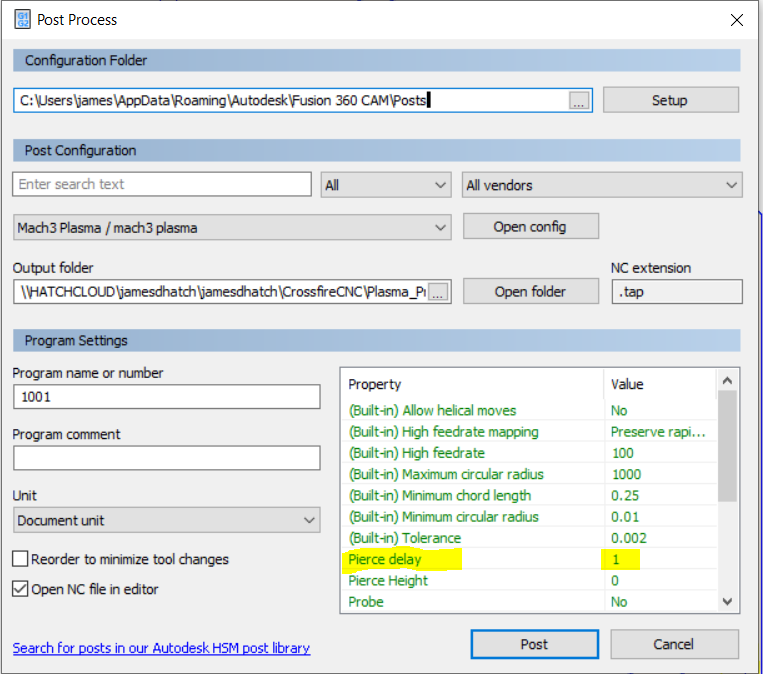
The pierce delay is going to show up on the right side of the G-Code generation window. There’s a set of text parameters in a box and about halfway down is the pierce delay. It probably says 1.0 and you just type over it to change it to something else.
1 Like
Yes it isn’t showing up there. I will post pic when I get to my computer. At first you thought it was I didn’t have something downloaded. I double checked all that and everything said “file already exists”
I would have to assume you did not create the crossfire tool or did not create it correctly in Fusion.
You can do this several ways but this video will set you rite. One done you will have to select the crossfire tool from your library each time you create you paths and process the file for the tap file
Also if you don’t already have it you will need the “mach3 plasma.cps” file
I believe this is shown in that video
This link should work
http://cam.autodesk.com/posts/download.php?name=mach3%20plasma
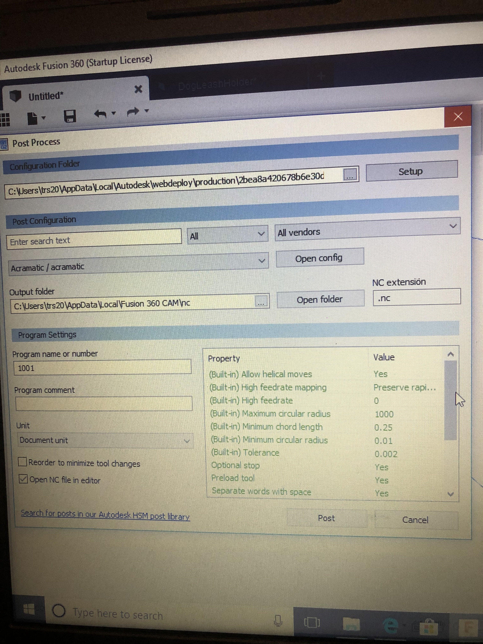
If you look to the left of the "open Config button in your photo and jamesdhatch photo his shows Mach3 Plasma / mach3 plasma your shows acromatic / acromatic
I think it all come down to these issues
After doing everything you just recommended (which I appreciate greatly) I still do not have piece delay option unfortunately.
Your file location is set wrong. You need to set the location to where you put the crossfire post file for fusion 360 at.
1 Like