Can anyone explain how the little red arrows work? I believe they are meant to show whether the cut is made on the inside or outside of the line. But they don’t make any sense to me.
That’s right. If the arrow is inside a shape, it starts and ends the cut inside and the kerf adjustment is made to the inside of the cut line. If the arrow is outside a shape it starts & ends outside the shape and the kerf adjustment is made to the outside of the line.
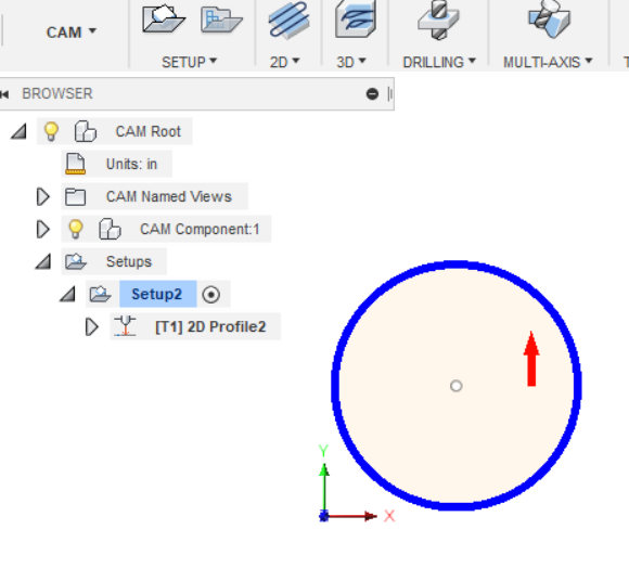
So this is a circle with the cut defined to be the inside - the arrow shows well inside the circle. (It can be hard to see on some small parts.)
And this is what it looks like after generating the toolpath.
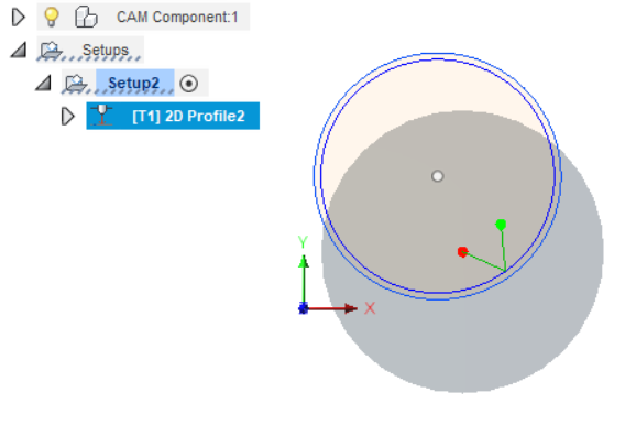
The big grey circle is the torch head - since the circle is pretty small the head looks huge. You can see that our circle turned into 2 lines. The inner darker blue line is where the center of the torch tip will go. The outer lighter blue line is our circle as drawn. The distance between the two is the kerf or how much metal will be burned away as the torch cuts. This is calculated based on your torch selection when you defined it for the toolpath. (As is the size of the grey circle - it’s based on the head size you enter when defining the tool.)
When it cuts, the resulting hole should be the same size as we defined the circle to be. The red & green dots and the arrows represent the lead in/out. The torch will back off from the kerf line the distance you defined for the lead in and travels at the angle you defined. Then when it finishes it will do the same thing. This prevents a hole on the track of the cut line because as the head starts & stops it sits for longer than it does when cutting so the kerf is larger - you end up with a notch or half a hole (the other half is lost to the piece of metal that will fall into the table). Your lead in/out puts that oversized burn hole in the waste.
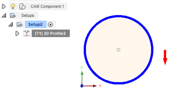
If we click on the arrow (I just edited the toolpath and went into the Geometry tab) it moves to the outside. It also changes direction because inside and outside cuts are made either “pushing” or “pulling” the torch - pushing in a clockwise direction is cleaner because that’s the way the air is spinning as it forms the plasma arc.
Here’s what it looks like after clicking it to move it to the outside:
And after generating the toolpath:

Notice this time the kerf adjustment (dark blue line) is to the outside of my circle (lighter blue line) and the lead in/out starts outside our circle. This will cut a circle of steel out that is unmarred by the lead in/out notches and should be the same size as we drew it. In this case the outside material is the waste because we want a little circle coin ![]()
In a more complex design you’ll have cuts both inside and outside your lines. Like this piece of my Nativity profile.
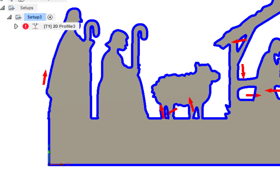
The profile is cut and shown by the red arrow on the outside on the far left. The piece under the sheep between the legs are cut inside and that piece will drop out leaving a clean cut on the larger piece. Same for the parts for the manger roof & beams. Some of the arrows are ambiguous - it’s hard to tell if it’s inside or outside so zooming in to make it bigger will help you see which side of the line the cut is defined for.
Make sense?
2 Likes
So maybe I’m just looking for your recommendations for cutting bolt and screw holes and alike. in the tutorial from langmuir they recommended lead-out offset and they use the lead in at .06 with a 90 degree curve and no lead out. What would your suggestion for cutting 3/16 holes and the 3/8 holes for lead in and out as well as angle. Your explanation shows straight cuts and no angles I’m going to try that I’m just a “little” confused. I do appreciate if you respond to this but if you don’t I really appreciate what you’ve laid out so far at least gets me trying other things.
Ah. I think the .06 lead in is too small. That’s my moving kerf width. I start by doubling that because when it’s starting a cut the head is sitting for the duration of the pierce delay. The longer it sits in a spot the bigger the hole. If the pierce delay is exactly what’s needed to establish the arc then the basic kerf would be okay - but it’s not, it’s either too little & you get no arc or too much and it burns a bit bigger.
So that’s why I double the kerf size for my lead-in. If it’s really thick stuff & I have to bump the pierce delay I may make it even more.
Then I leave the default radius & angle (60 degrees) and see how the path generates paying attention to the lead in/out lines. It seems that it would be more efficient to use a 90 degree angle but that means the head makes a sharp turn entering the cut and simple mechanics says that’s not as smooth as a gradual entry.
The size & shape of the cut out impacts your choices too. You may have room for a nice shalliw lead-in but the lead-out doesn’t so you have to adjust.
For machining purposes where you’re cutting bolt holes now you have to think about the thickness of the material. As the material gets thicker you’ll get a larger slope effect on the cut. That’s caused by the way the arc is shaped - it’s not a cylinder of plasma but more of an hourglass shap with the narrowest part (hopefully) focused right on top of the material. It spreads out as it travels through the plate.
If it’s thin stuff (guage measured) it’s not really much of a difference in the size of the arc and thus the hole at the top vs the bottom of the sheet. As you go bigger you’ll actually be able to see a slight slope to the cut. That makes the top of the hole a slightly different size than the bottom. So for thick material or where precision is required define the hole slightly smaller than you need. Then use a step drill to drill it out to the exact size you need. It’s an extra step but you don’t have to drill qtr inch steel all the way - just opening it up a little. That’s faster and easier on your drill bits.
So for your 3/16" holes you’ve got room for a larger lead-in than .06 but not a ton because the hole is only 3 times that - too much lead-in and you’ll run into the other side. Keep the pierce delay as small as you can and still get the arc and use a sharp (90 degrees even) angle because you don’t have a lot of room for shallow entry.
And if it’s 1/8th or 1/4" plate back the size of the hole down a little so you can finish drill it afterwards.
Thank you so much for the detailed explanation. I have read several of your posts and always learn something. I think the problem I was having with the arrows is that what I’m cutting is fairly small (one inch tall letters) so the arrows are always outside the letter just in different places. I’ve been practicing with the Langmuir bottle opener adding my name to it. I have cut a large amount of them trying to get it looking good. Mostly the problems I’ve had are in the setting for lead ins, angles and distances. Is there a minumum area size that can be cut?
Attached is my best work to date, cleaned up with a little Dremel work.
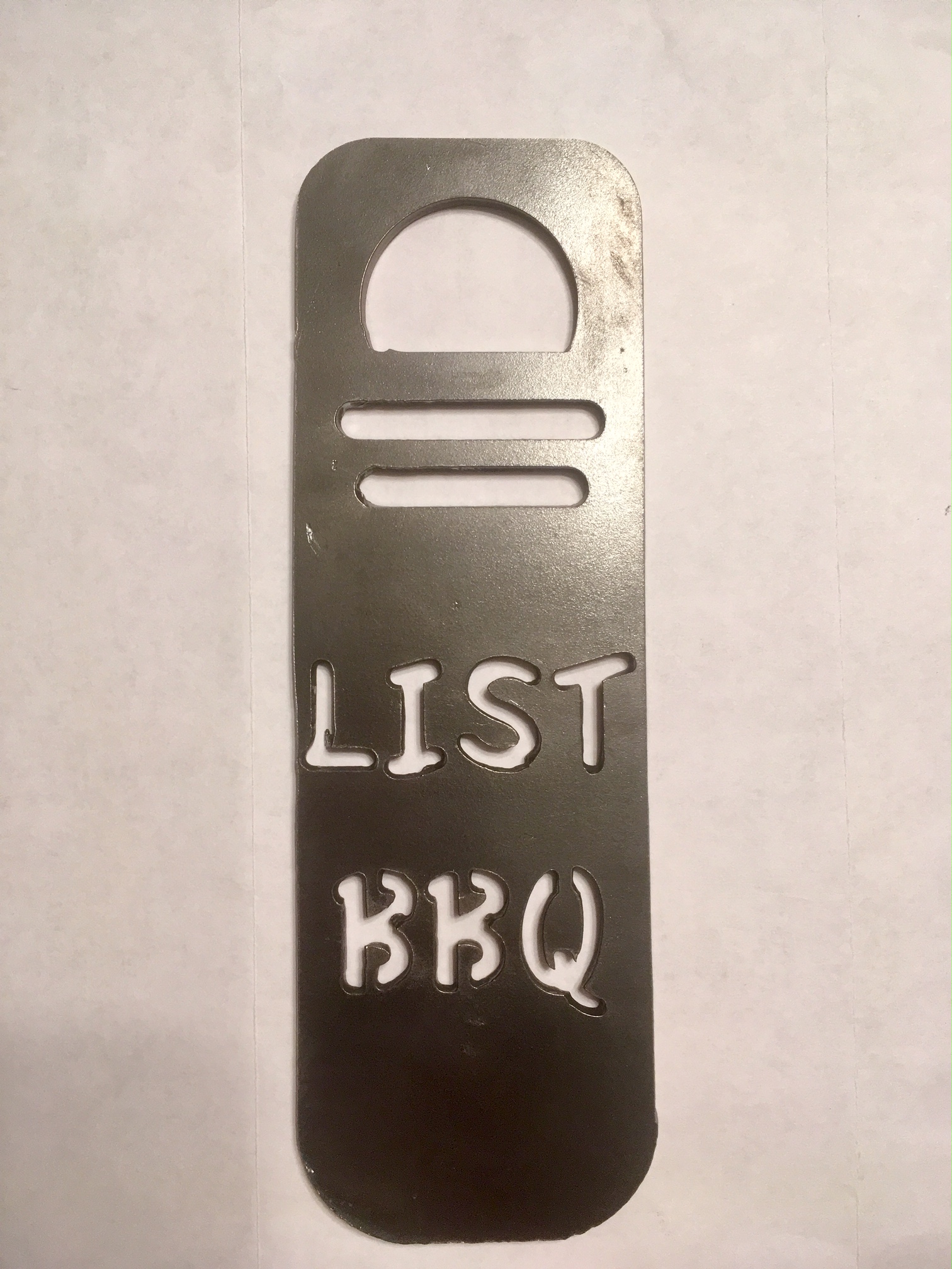
Thanks again for the help, the learning curve is a steep one.
I found that turning the text 90 degrees allowed larger fonts