While I’m trying to generate a tool path I select the part that I want cut out but after that when I select what lines need to be cut it will not select any lines just makes one big line through my part. Has anyone ran into this problem? I have watched all tutorials multiple times and haven’t figured out where I am wrong yet. Any help is much appreciated.
1 Like
Did you click on Setup before you started defining the toolpaths?
I’m doing step by step just as the tutorials show.
Follow Jims advice. He has helped me tremendously in getting the programming figured out.
Do I need to click the setup button at the top of the screen or on the left? After further thought I think you are right I click the cutting icon and go straight into defining a tool path.
On the left. I can do a step-by-step with pictures tonight if that would help.
If you want to post the file I can use yours for the instructions.
All I am trying to cut is a simple circle because I haven’t been able to cut anything in the 4 months I’ve had mine.
I have created a tool path now and can simulate but when I save as a sat file and load a g code into Mach 3 I am getting a bad character status block 700 0 1 0
Okay, here’s a step-by-step of a circle with pictures ![]()
Start a new session of F360
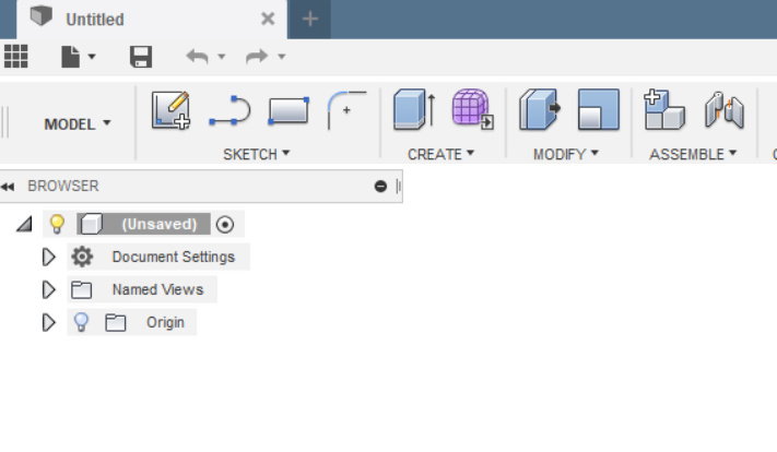
Click Sketch|Create Sketch
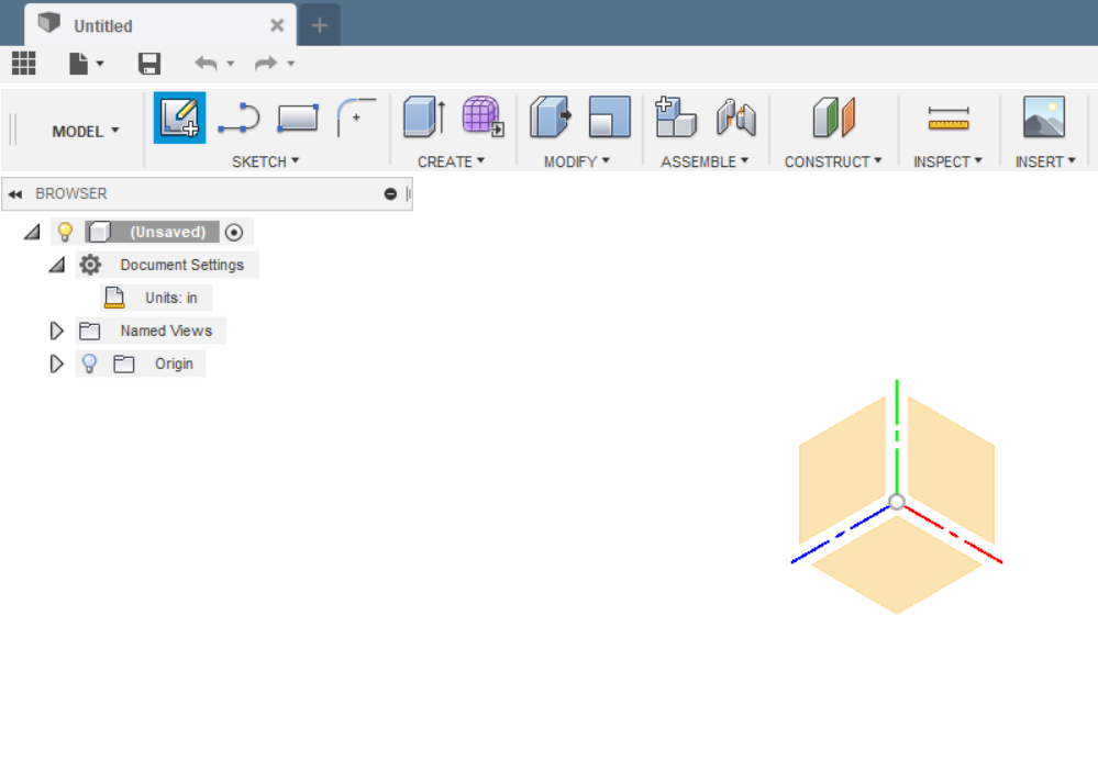
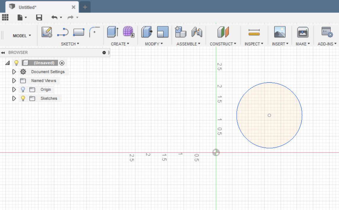
Click on the front face - the circled one to set the work space and origin.
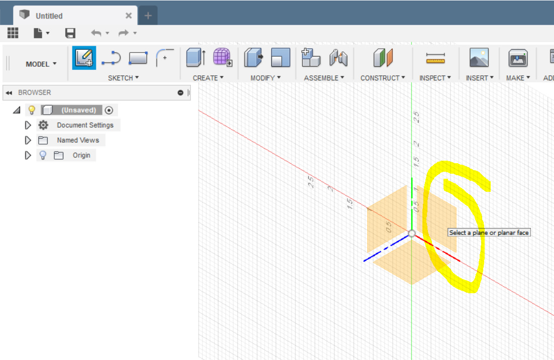
It should look like this:
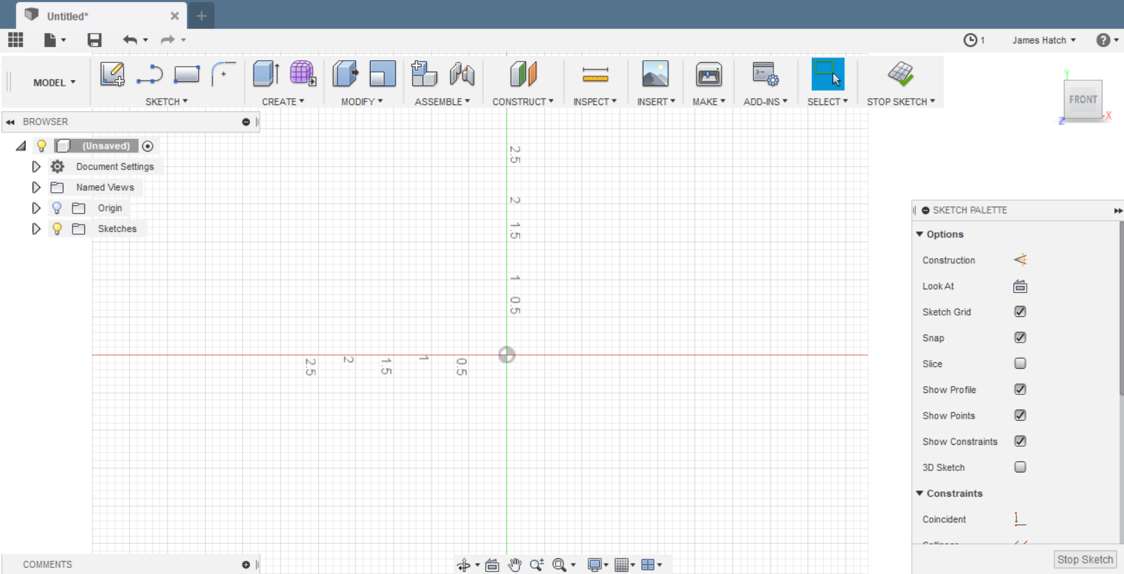
Click Sketch|Circle and then pick a type - I used 2 Point circle and dragged it on the canvas like this:
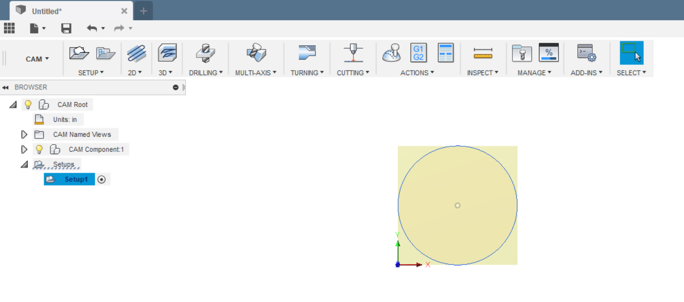
Click on the Model menu item and in the dropdown choose CAM
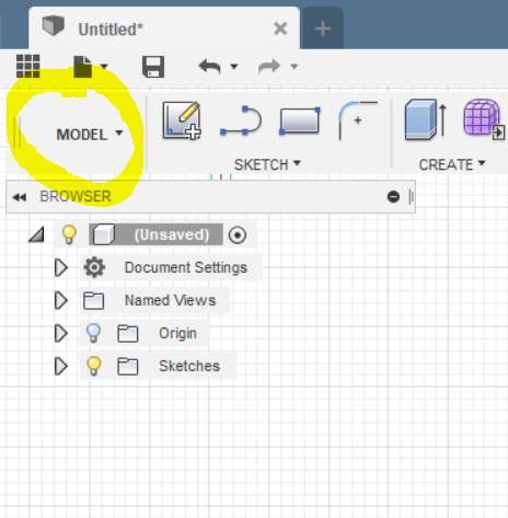
It should look like this:
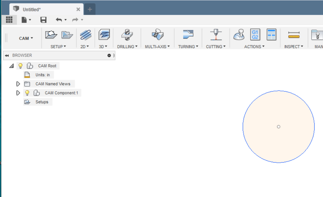
Click on Setups on the left tree and it will highlight like this:
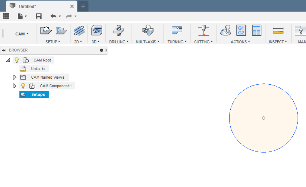
Click on the Setup|New Setup in the menubar at the top and you’ll see this:
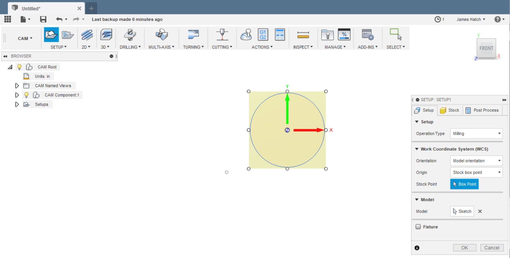
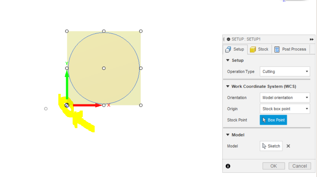
Fill out the po-up on the side defining the Setup like these pictures. Pick Cutting for the Operation type, I pick the Stock box point as the origin and click on the lower left corner to define the box point. This is going to be where I set Mach 3’s X/Y origin. I tend to use the lower left but there’s nothing sacred about that - you could use somewhere else if you wanted to.
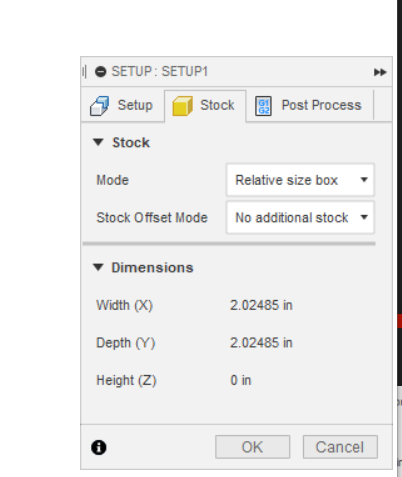
Then in the Stock tab I choose No Additional Stock in the Stock Offset Mode dropdown entry box. This means it won’t add extra space around my cut - you’d do that if you wanted to do some after cutting finishing so you leave a bit more material that you’d grind down afterwards which we don’t need to do on this part.
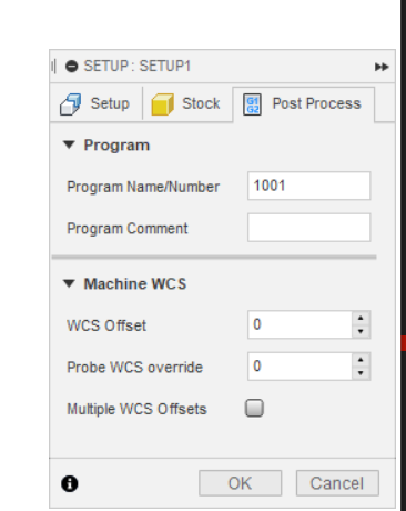
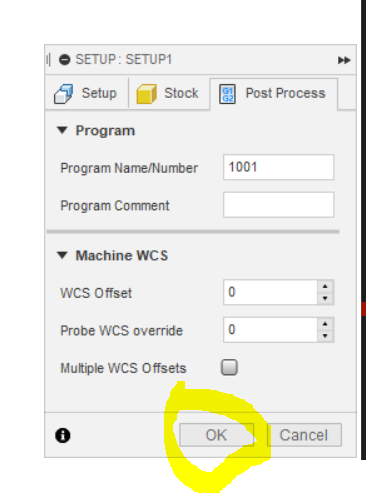
In the Post Process tab you can leave it or name the program (the G-Code we’re going to generate) and add a comment. These will transfer over when you post-process to create the G-Code but you can also enter them at that time too. Mine looks like this:
Click OK in the setup box.
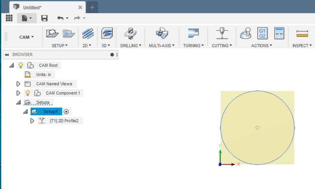
It should now look like this:
With the Setup1 in the left side tree still selected (it will be highlighted blue), click on Cutting in the menu bar
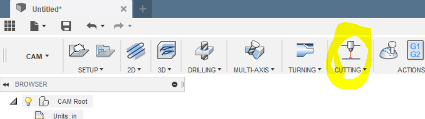
It should now look like this with the 2D Profile pop-up on the right side. This is where you’re going to define the toolpath.
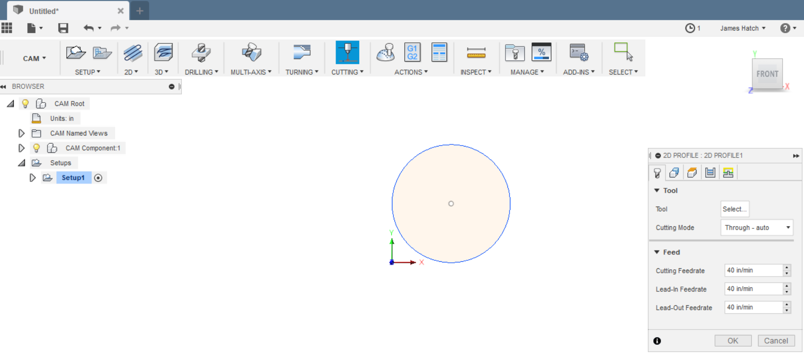
Click on Tool Select in the pop-up and you should see this window pop-up and clicking on Library should show you a cutting tool defined - if you followed the Langmuir tutorials. If you’ve setup other tools (you’ll do that if you want to fine tune things by power or tip/nozzle size), they’ll be here too. I’ve got the one defined on this computer.
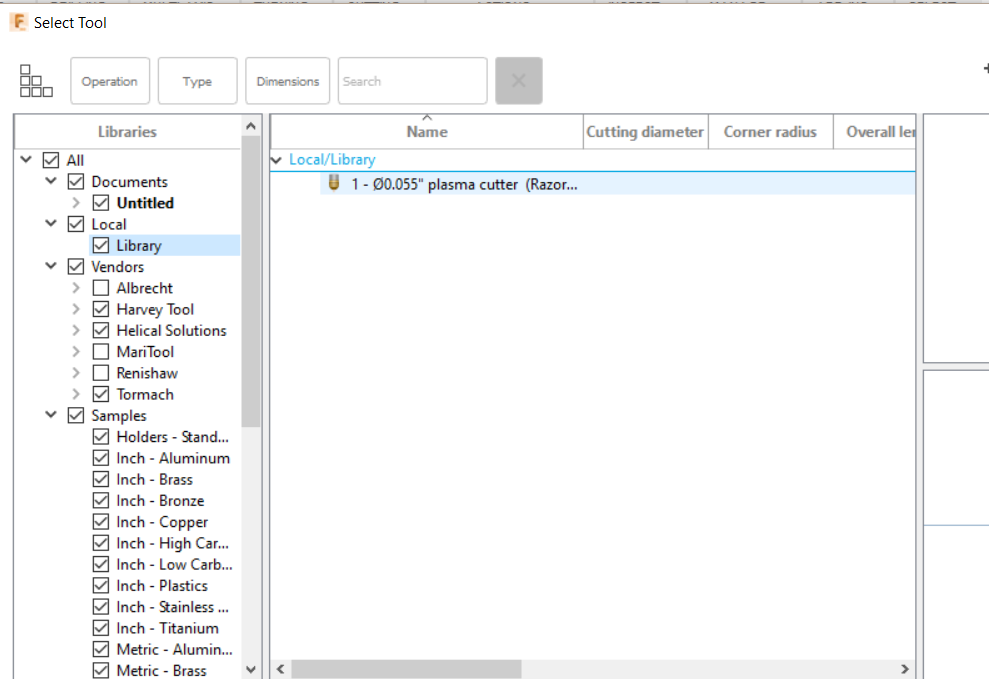
If you haven’t followed the tutorial and don’t have a tool in your library you’ll need to create one. But assuming you have one, pick it and you’ll see this:
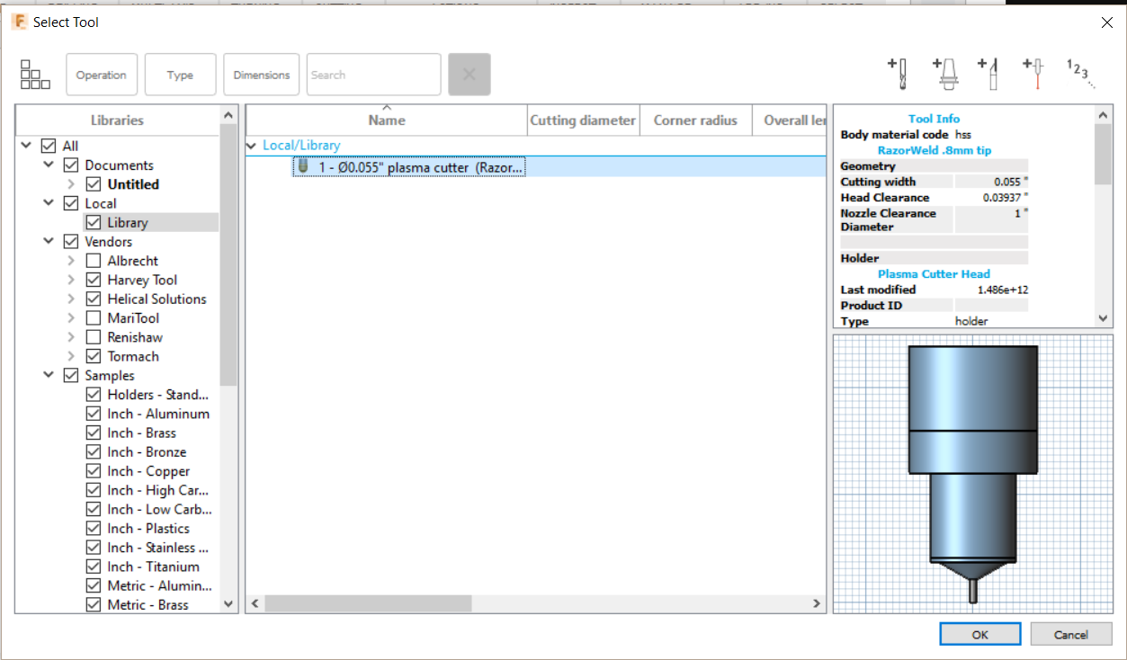
Click OK
Your screen should look something like this:
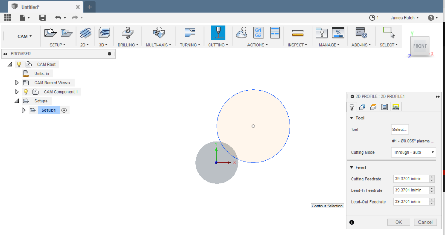
You can change the default cutting speeds in the first tab of the pop-up but we’ll leave them for this test.
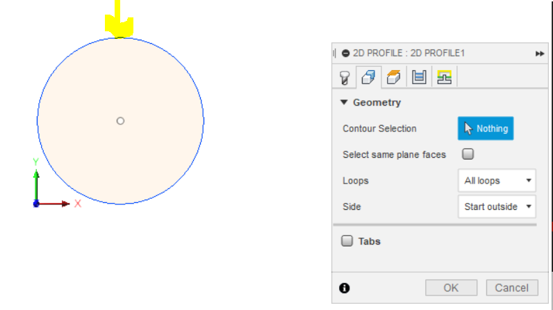
Click on the 2nd tab (Geometry) and it should look like this:
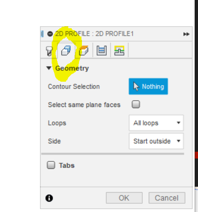
The Contour Selection box is where you’re going to pick the path in your model (the circle) that you are going to cut. On a complex design you can pick all the lines you’re going to cut but for now we’re going to click the Nothing box and then move the mouse pointer over the circle’s line which should turn blue. Put the cursor over the line somewhere - the thin blue line will thicken.
Click on it and you’ll get this:
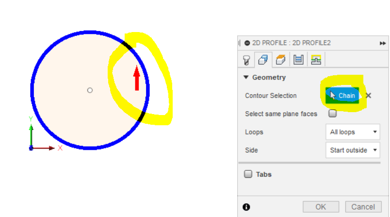
You can see where the line is now a thick blue and there’s a red arrow inside - that means it’s going to start the cut inside and move to the circle and cut it out. The Contour Selection box now says “Chain” indicating it’s got a toolpath defined - when you do complex designs it tells you how many lines or “chains” it’s going to cut.
Set like this, the waste part is the circle of steel. If you wanted to have a circular piece of steel and leave the outside as the waste, click on the red arrow and it will move to the outside like this:
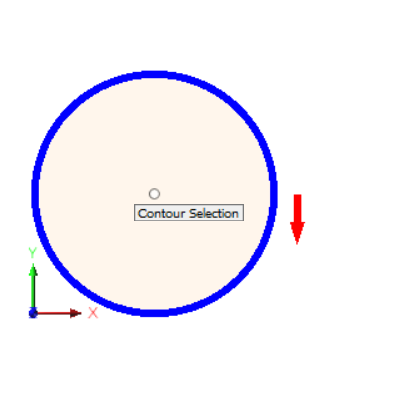
Leave the rest of the info in the Geometry tab the way they are - you’re going to cut all loops and it will start on the outside.
You can skip the 3rd tab - Heights - as there’s no Z-axis (height) control with the Crossfire.
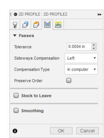
Click on the 4th tab - Passes.
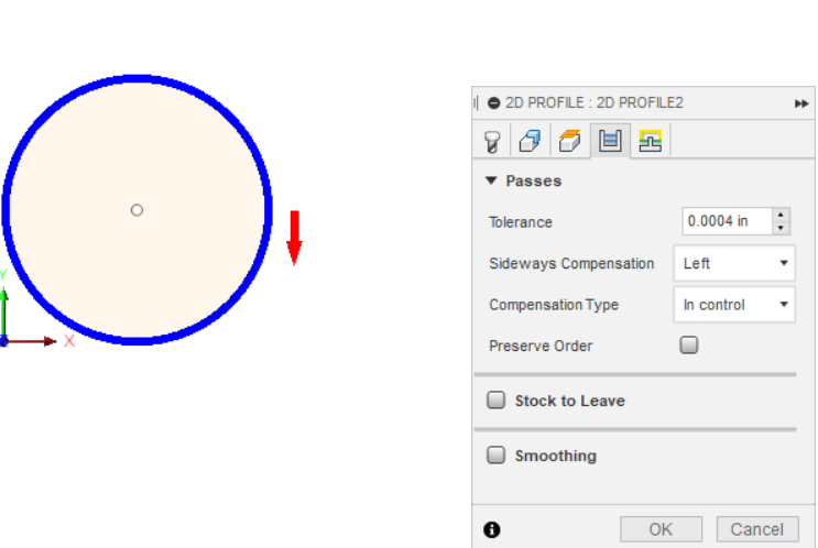
Set the tolerance really small if it’s not already - I have 0.0004 in for mine because my computer is good and I want nice smooth lines. Bigger tolerances are easier to calculate but don’t give you as smooth cuts. Leave sideways compensation as Left. This is how it compensates for the kerf and CNC torches cut best with left side comp because of the clockwise swirl of the gas coming out of the nozzle, the arc swirls from left to right and the cut is cleanest coming from the left. Change Compensation Type to “In computer” - this way the path is defined with kerf compensation. (Kerf is the amount of material your arc is going to vaporize - it’s like the width of a saw blade on a table saw.) If you don’t use In computer, you would be expected to set that up on the machine (using Mach). Much better to let the computer (Fusion) do it now. It should look like this when you’re done:
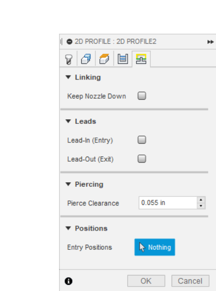
Click on the 5th tab. It will look something like this (don’t worry if you have other entries - Fusion tries to reuse values you’ve used before to make it easier on you to do repetitive work):
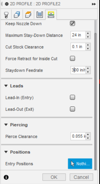
Click on Keep Nozzle Down because we don’t have head retract capability on the Crossfire and it will change to this:
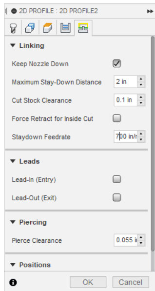
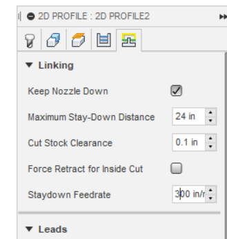
Change the Maximum Stay-Down Distance to 24 or something bigger - this will prevent generating G-code that tries to tell the Crossfire to lift the head when moving to another part of the design before firing again. Not an issue with a single line circle cut but it would be if we had more lines to cut. Change the Staydown Feedrate to 300 which is the max the Crossfire can do. This is the speed it travels from one cut to the next - not something we need to worry about on this design but it can help make jobs faster when you’re doing bigger more complex designs with lots of cut/travel/cut operations.
It should look like this:
Use the scrollbar on the right if you need to in order to see the rest of the entries. Like this:
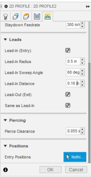
We’ll add a Lead-In (where the head will start outside the line to pierce and then move in so you don’t get an oversized pierce point on the line itself which would result in a notch in the circle of steel we’re going to cut out). The lead-in radius is how much space the lead-in curve will take - in this case we’ll pick a half-inch. Sweep angle is what angle it will take coming into the line. We’ll pick 60 degrees so it slides in at an angle to make it a smoother gradual entry. Pick a lead-in distance which is the length of the lead-in and needs to be greater then your kerf so it starts far enough outside the line that the kerf from the pierce doesn’t overlap the line - I choose 0.16 or about 3 times my kerf to allow for the pierce to be made because the pierce has a larger kerf than a moving cut because it has to establish the arc and hold it for the pierce delay. Keep Lead-out and Same As lead-in checked. This will have the same extra bit of cut on the way out of the circle as on the way in and prevent any overcut on the circle itself & thus a wider bit of a hole when the cut is finished and the torch moves off it. Your pop-up box should look like this:
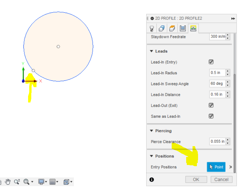
Almost done. We leave pierce clearance as defined in the tool definition but we want to give it an entry position - where it’s going to start. So click on the Nothing box next to Entry Positions and then a point on the circle we want it to start on. I picked a place near the lower left because that’s near the origin of my design and where I’ll set Mach 3’s X/Y 0,0 and it will keep the head from having to travel a bunch just to get to where it will start the cut. You’ll also see the Entry Position “nothing” box now says “Point”.
We’re done creating the toolpath and we click OK. That’s going to generate the toolpath. It’s going to be quick so you won’t notice anything but the left side will update with a line under the Setup for the toolpath. For complicated toolpaths with lots of chains you’ll see it calculate as it shows its progress by updating a percentage value until it’s done.
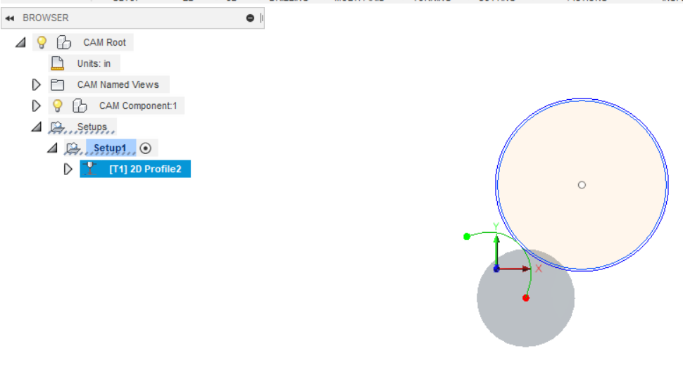
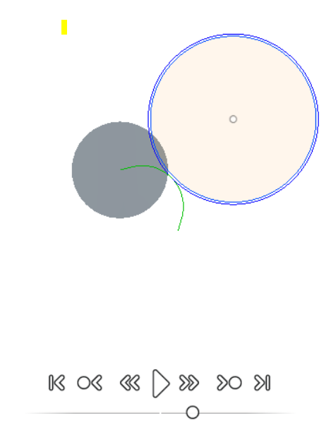
Notice under our circle there’s a big gray circle - that’s the head of the torch and you see a red & green dot connected to the circle’s border by a green line. You can also see that the blue line of the circle is actually 2 lines. The green line is the lead-in and lead-out where the head is going to start outside the circle, pierce and then move in and cut the circle before moving back out and then finishing. That will leave a nice clean circle of steel. If you wanted a clean hole instead, you’d start the path on the inside of the circle and the lead-in and lead-out would be in the circle piece of steel and would leave a clean hole instead. The double blue line of the circle is not that it’s going to cut twice but shows the circle you defined (inside) and the center of the torch as it cuts - the gap is the kerf it’s going to leave as it cuts so the circle is the size you specified and not something less because the arc takes out some steel as it vaporizes it. (Technically it’s 1/2 the kerf because there’s an equal amount being taken out on the other side of the center of the arc as it goes around.)
Now we can see if this is going to work. Click on the setup (Setup1) on the left and it will look like this:
We’re going to simulate the cut and by picking the Setup, we’re going to get all the toolpaths we defined. In this case it’s only one, but if you decide to do multiple paths you’d pick them all up this way. You might want different paths defined on a complex design if you want to change the lead-in/out for some small cuts vs what you’re doing for the larger parts of your design or you might want different speeds if you’re trying to dial in the settings for a material/power combination.
Click on the Joystick icon on the menubar or click on Actions and Simulate.
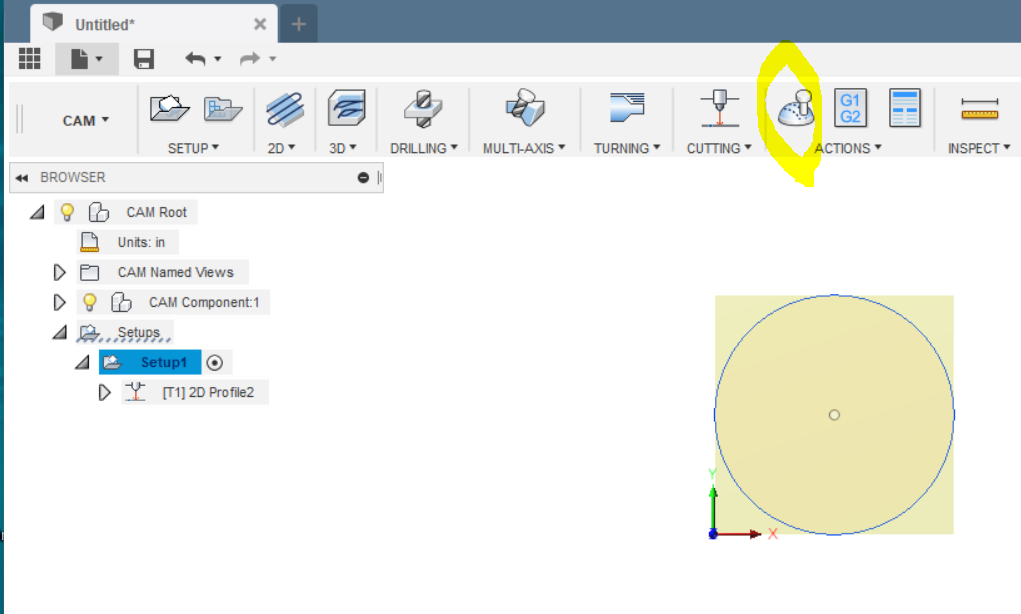
You’ll see this:
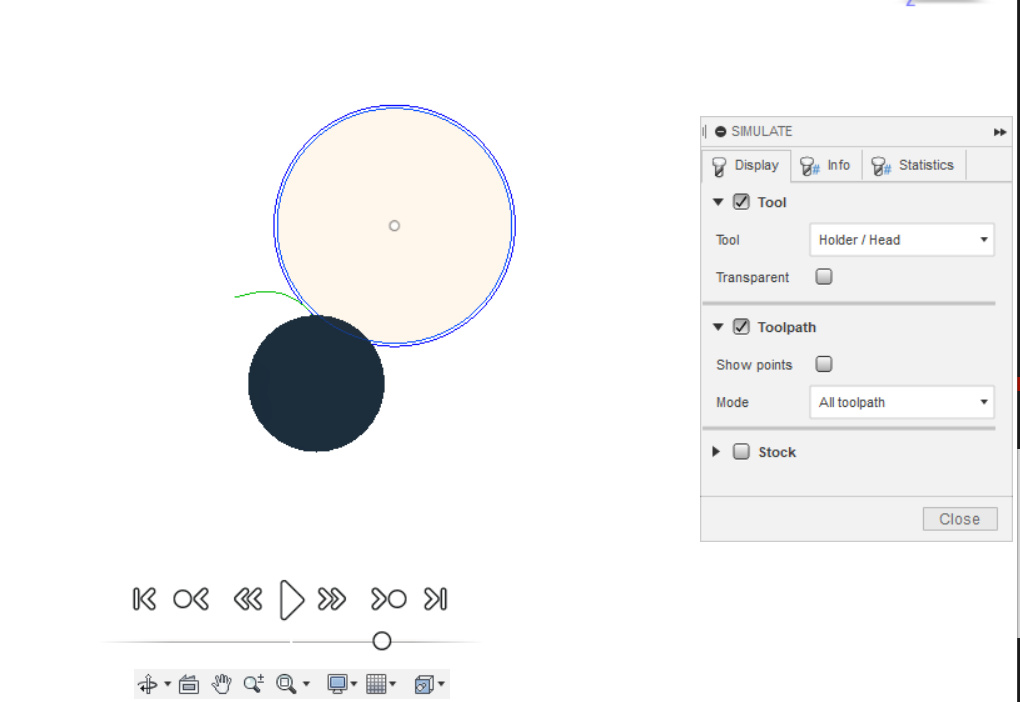
I click on Transparent in the tool section so I can see the movement of the toolhead simulation over the path better - not a big deal on the circle but when you get to complex designs it’s useful to see if it really is traveling over all of the cuts or if it’s skipping some. I leave the rest alone generally (later you can play to see what the options and tabs do).
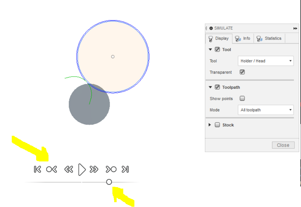
Notice my toolhead simulation is now gray so I can see the lines under it. Also, you can see the controls on the bottom of the screen like a VCR and the line underneath with the circle - that one controls the speed and direction of the simulation. The big > in the center starts it. Click that and you’ll see the tool start, pierce, run the lead-in, go around the circle and then come back off of it to where it will end.
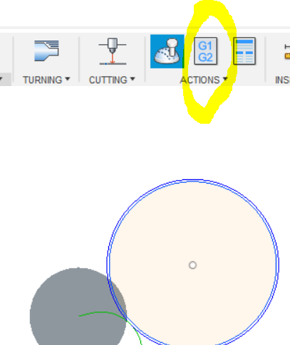
It looks good so our next step is to generate the G-Code. Click on the G1G2 icon on the menubar or pick Post Process from the Actions dropdown.
You’ll get this:
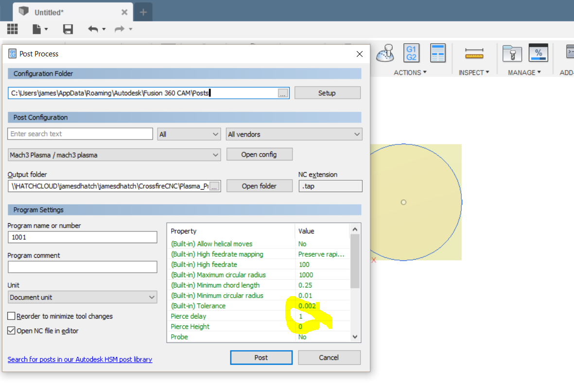
This is the control setup for the G-Code you’re going to have Mach 3 process. The highlighted circle shows the Pierce Delay setting - I use 0.5 but the default is 1 second. That’s how long the head will pause at the beginning of cuts to trigger the torch and arc and then wait while it pierces the material. The thicker the material the longer this needs to be as it takes longer to pierce it. But the longer it’s on after it pierces the larger the hole caused by the arc gets so you try to keep this to something that establishes the cutting arc but isn’t overly long - it’s also why you want a lead-in/out setting as the pierce hole is going to be bigger than your kerf and if you start the cut right on your lines you’ll get a little hole from the arc pierce that’s wider than the cut that it’s going to make once it’s moving. The settings in this window are the ones you’ll have made when you setup F360 and Mach 3 on your machine. You can change the program name and comment on the left side - this is the CNC G-Code program not the Fusion or Mach 3 program.
Click Post and you’ll get a standard Windows filename dialog box:
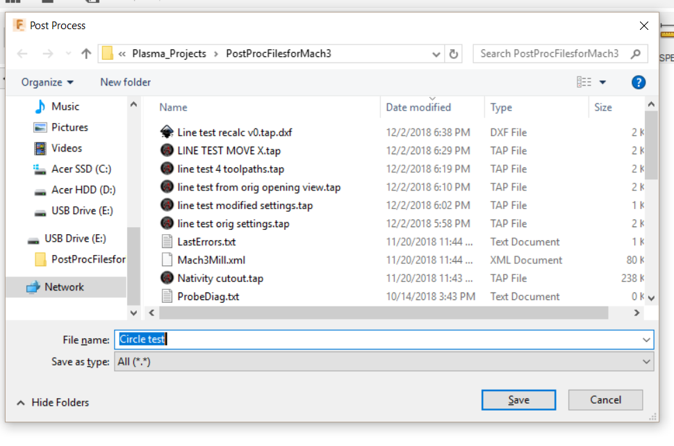
Click Save and if you left the “Open NC file in editor” option picked it will open the G-Code in an editor and it should look something like this:
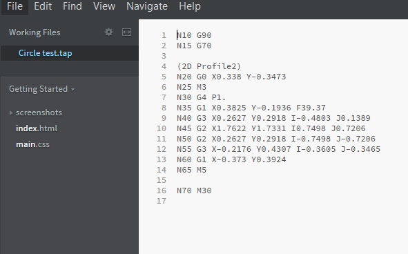
Pretty simple G-Code because this isn’t a complex design. Doesn’t take much to cut a circle ![]()
Let me know if you get stuck somewhere along this.
3 Likes
When I click on the g1 g2 tab I do not have the pierce delay tab.
Do you not see the G-Code generation information or just not the place for the pierce delay?
James that is one of the best detailed posts i have seen. It told me so much that i missed watching vidios. I have been struggling also. To many other things going on to focus on the vids. I thank you for your time and effort to this site. This should be in the main site menu as a beginners guide. Thanks Jim
1 Like
Thanks. I like videos but it can be hard to catch all the steps sometimes. Click by click directions with pictures can be more helpful - especially if you print them out and just follow along.
But we’re a video culture now so that’s where most of the attention is 
I have g code generation tab open just no pierce delay in green column
It may be lower down depending on how big the window is on your monitor. Did you scroll down to look for it in the Properties Box?
Yes. I couldn’t find it. I appreciate all the help by the way.
You installed the Crossfire Mach3 Fusion 360 Post?
What do you mean? I have Mach 3 and fusion 360 yes
James. When i pick the tool. Same as your picture. It shows a tool head above it instead of a circle like yours. And when I click the nothing in the geometry tab and move over to the circle it highlights it but when i click it it puts a horizontal line under the circle. Like its sitting on the blue line ,a red arrow each side pointing inward. Im thinking a setting issue?. Thanks Jim
hi Tanner. On this sight on the downloads where mach3 download is. There is a download for mach3 fusion 360 post. You have to download it and put in the proper place to post process your projects in fusion to put it in your file so you can use it in mach3. If that makes sense. there is a vid on post processing i beleive. I had trouble with it for awhile. Not sure where you at on it, hope it helps but . I really no nothing really yet.