So I’m thinking about doing a simple modification to add some z-height to compensate for adding a fixture plate and smw vise and also to raise the working height for future plans of a 4th axis add on I plan to build.
The idea is to simple add 2 square blocks between the X axis gantry and the y axis cast iron carriages. With this I could effectively add as much height as I want with the added torque on n the linear rails as the sacrifice.
That said the main feature of this machine is in my opinion the beefy rails. The gantry router I built has this same size rails and 2505 ballscrews. And they can take a large amount of torque.
@langmuir-daniel you guys fae the current setup vs a higher setup in terms of torque stress analysis on the gantry/rails?
My plan is to add 2” thick block and make some longer bolts to replace the stock ones. Might end up moving up a bolt size but probably only if I make a mistake lol.
I’d like to hear opinions on this and if any Langmuir guys have done the simulations and know the danger point, please do share. If anything I’ll probably
End up doing the simulation myself eventually.
Funny you mention this. I just bought some 4" X 11.75" steel bar stock for this purpose today. My plan is to cut it in half, and use each piece to make these risers (keeping the top and bottom precision ground surfaces untouched). An inch isn’t a huge lift, but it’s enough to compensate for my extra-thick base plates. They will add ~7.25 lbs to the gantry weight (total), but I prefer steel-on-steel to sandwiching aluminum between ferrous metal parts. I’ll be parkerizing them to match the rest of the machine and for corrosion resistance.
very nice! i planned on winging the precision part myself but putting it on a brick and mortar manufacturer is way smarter.
I was thinking worst case scenario is we need to edit the X ballscrew and motor. I really hope Langmuir decides to make a X,Y, and Z axis upgrade add-on. i have a feeling there will be wants for all of them. once we start to hit the limitations of this machine. and with all the money we saved opposed to buying a tormach i am totaly down to buy a axis upg. lol
Ill probably dd at least 2 inches so my worry is the added lever arm and the added cutting force on the gantry and not so much the weight of the X axis.
50 bucks each for a precision flat riser that just needs some material hogged out of the middle is a pretty unbeatable. I might even core out the middle with a waterjet to save some time. ±2 thou could be better, but I’m hoping that’s over the whole length, and by cutting it from the same stock I can at least get two pieces with similar degree of tilt. I might lap them a bit if they need it.
I’m no expert in this regard, but it’s also worth considering that additional moment force would also probably cause extra wear on the Y linear rail bearings and rails. Ideally, with a taller lift you would commensurately increase the length of the Y carriage castings for a better footing on the rail, but you’d obviously sacrifice Y-axis travel for that.
that’s exactly what i was thinking. from the FAE I’ve done that torque either hits mid gantry(with cheap aluminum gantries or on a moving connection to the base. and since this is a moving gantry type itl most def hit the Y carriages. But Langmuir sprang for beefy rails so worst case you end up getting chatter when working steel or have to take easier cuts in steel which im good with as long as i have more room.
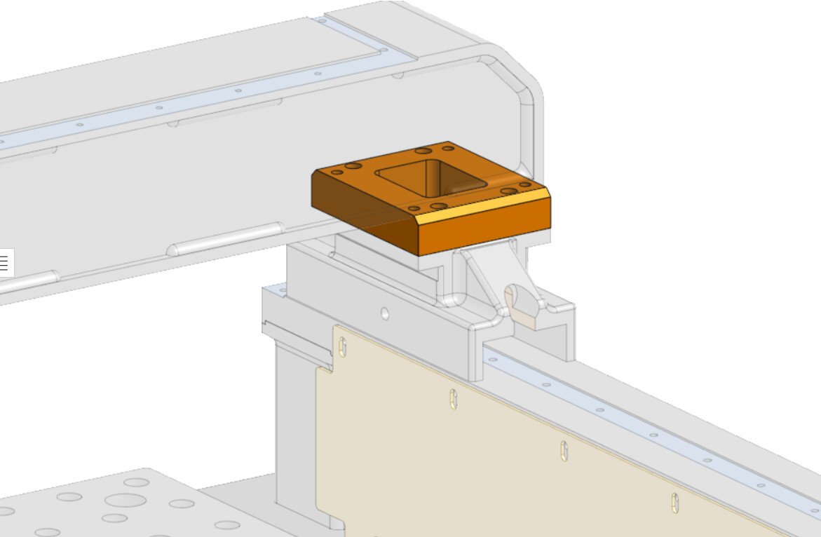
My own reverse engineered CAD, since Langmuir is reluctant to share a model. It’s not complete by a long shot. I will put it online once the whole assembly is modeled - right now it’s a pretty big mess.
I also plan to have 2" more clearance to the X-axis carriage, but my plan is to do it in two areas.
I raised my y-rails in the pan 3/4". To do this, I added some additional side and bottom gussets to the vertical Y-rail tubes, made new taller and wider side plates that bolt to the Y-rail vertical tubes, made brackets that clamp the Y-rail vertical tubes to the legs and then filled the opening below the Y-rail bar with concrete.
I plan to have a 1 1/4" Y-X spacer, but currently just have 3/16" ones which will get me to 6.5" X carriage clearance.
I just finished up my risers. I milled them from precision ground flat stock, didn’t touch the top or bottom (except to deburr with a benchstone), and they maintained very good flatness and parallelism even after hogging out the middle. Flat and parallel to about 15 microns over 10 cm.
Happy to share the CAD if anyone wants it. Feel free to DM me.
One thing I did notice… if the riser is too tall, it might not be possible to insert the screw up through the Y rail castings without additional modification, because the screw would need to be so long that there would be an assembly interference with the casting itself. 1" riser is safe, but it could get tricky if the riser were any taller.