Was all over the place trying to get Z axis travel dialed in… ended up taking out all the shims to get a base line. 2/4/6 block on base plate. 4" travel in Z facing front. I have 0 at top and a plus (towards front of machine) at bottom of .0075. I was thinking it needed to be parallel with shims at bottom but now thinking I need to add bunch of shims at top… which made me lose all concept. Suggestions which way to shim this?.. and how many. Don’t even think I have enough of the labeled bottom shims (10). .0075 would take 6.25 of them on each side. Mentally loosing it! And something really confusing… I can push towards back with my hand on top of spindle housing at bottom to “zero” it but by the time it gets to the top I’m pulling on the housing to keep the same “zero”. Like it needs shims at bottom when at the bottom but seems to need shims on the top when at the top. Ugh!!
Getting the Z axis dialed in a few times on my machine has been a hair pulling experience. Only multiple times due to removing the spindle and doing some modifications here and there.
My suggestion is to keep track of how much shim you add and the readings before and after.
Start with as plain of a number as you can. So say .005" shim if you have that size.
Add the shims and see what the reading is, for example:
+.0075" to the bottom w/ 0 shims
added .010" shim, new reading +.004"
Now you know that .005" shim made a .0035" adjustment at the table. Meaning for every .001" of shim added you should see ~ .0007" of adjustment.
[.0035" / 5(.005" shim) = .0007"]
Therefore .0075" error should theoretically take .0107" shim to correct.
[.0007" x 10.7(.0107" shim) = .00749"]
(All just random numbers for example btw, I can’t recall what shims I ended up with or how much each shim did)
That’s the easiest way I can offer to dial it in. Make an adjustment and see how much it changes and which direction it changed. Also, in my experience, the torque applied to the (3) lower mounting bolts was enough to affect the squareness. So if you’re within .0005" over 4 or 6 inches in Z you can slightly adjust the torque to bring it down to 0.
I probably made that sound way more complicated than it is, but you’ve got this. Take your time and measure everything multiple times. Heck flip the block over and check the opposite face to make sure a hair didn’t end up under it. A hair is about .0015" ![]()
Not to put more on your plate, but after you get the Z travel all squared away you’ll probably want to check your nod and tram. I’m not sure if they ever put up the video on dialing that in, but if you need help with it just post up here and I’m sure some of us forum dwellers will chime in to give you a mental helping hand ![]() Again, just take your time and keep track of what each adjustment came out to.
Again, just take your time and keep track of what each adjustment came out to.
Will digest this input and report back. Appreciate the feedback!
Well… got Z to .0005. Problem is… No shims in top and .025 worth of shims in bottom. With .0005 think I would be good but when I faced off the base plate prior to checking Z it came out pretty good. Cant feel any steps and the vise sticks to it. After getting Z to .0005, started the base plate facing program to skim the base plate by .003 and stopped it about 2-3 paths in cause I notice a very small step between passes, Its really small but just the fact I didnt have any step prior to getting Z good and now placing .025 worth of shims which results in a step now… Just crazy. The step is small so how .025 worth of shims only went from no step to a small step is curious. At this point… gonna leave the base plate as is… smooth and get to the point to face off an actual part and see if there is still a step. Then maybe back off the .025 shims to find a happy medium no matter what Z measures. Oh… and the calculator started me off with no shims in bottom and 4 on each side at top. It did give me a flat base plate but Z didnt look good from a measurement standpoint. My spindle left to right tilt is less than .001. Not going to mess with that at this point.
Well done on the Z axis alignment. Every drill you run and deep shoulder you mill will be better because of it ![]()
Now you’re seeing some nod in the spindle. It’s going to be a shim job also, but nothing major. I’ll write it out as step be step as I can think of and get you pointed in the right direction (or a direction at least ![]() )
)
This is all going to be based on you having a way to mount your dial indicator in the spindle via a stem setup or Noga articulated arm. If anything doesn’t make sense leave a reply and I’ll try to clear it up. Also that tram amount from left to right isn’t a bad starting point. It may change during the nod shimming steps, but it can be dialed in easy enough later (and no shims!)
Start off by removing the sheet metal shroud over the spindle and mounting your dial indicator however possible so you can sweep a 4-6" diameter at the sensing end. You’ll probably want to use either the bed of your vise or a 2/4/6 block to have a good flat surface to check this on since the baseplate is not exactly flat. Check that you have access to the hex head bolts that go through the Z axis carrier into the spindle block. They are about 1-2 inches up from the bottom of the carrier plate. so you may need to jog the spindle down some to have access.
Turn the spindle by hand and get your reading from front to back. Chances are it will read a + in the back and - in the front given how you had to shim the Z axis. Take note of your readings and do the same as before, add a shim, check the reading and adjust accordingly.
First loosen off the spindle block mounting bolts, which depending on your spindle position may be slightly different. There will be two hex head bolts that thread into the rear of the spindle block. 2x SHCS (Allen head) bolts that bolt through the side plates/gussets into the spindle block. and possibly 2x 1/4"-20 SHCS bolts going in from the front upper area of the spindle block into the Z carrier plate. Those will be there if the spindle is in the raised position. Break all of these loose about 1 turn, maybe more if needed.
Add your shim between the spindle block and Z axis plate at either the top or bottom depending on your reading. (Top is what I’m going to assume). Tighten the bolts down from top to bottom and check your indicator reading again.
You may see a larger reading in the X direction than you did before assembly. Don’t worry about that yet, because it’s way less headache to dial in after the nod is adjusted. Just try to get as close as you can in the Y axis direction for the time being.
Figure up how much shim you added, vs the reading on the indicator and add or subtract shim until you get the nod dialed in as close to zero as you can.
Any nod amount just becomes increasingly noticeable as your tool diameter goes up. For example I use a fly cutter set to around 4" diameter on aluminum plate and I dialed in my nod to ~.001" over 7 inches. That means over my 4 inch cutter diameter I’ll only see about a .0005" deviation. Way closer than your average home user would need, but I want it to be accurate dang it ![]()
For what it’s worth I think I ended up having around .016" or so shim at the bottom of my z axis to correct the Z perpendicularity. The calculator recommended .0078" on top or something like that. I tried everything I could to make their calculator make sense, but it was a hard miss for me
For your tram adjustment in the X axis direction you’d break loose the same bolts to where they are just snug.
Sweep your dial indicator over your flat surface and tap the spindle with a dead blow or rubber mallet to roll it in the right direction so that your X axis reading is as close to zero as possible and tighten everything down. See, easy compared to all the other stuff you’ve done to get to this point. ![]()
There have been a few of us that added some 1/4-20 through holes to the side plates/gussets the mount to the spindle block. These help hold the spindle in position better than just the bolts and keys that are originally holding it in place.
In the future if you have a tool break, part come loose, or something else that causes a decent bump on the spindle, check your nod and tram real quick by mounting your indicator in the spindle and sweeping a flat surface. Chances are your nod will still be good, but the tram may have slipped one way or the other and you’ll need to knock it back straight again.
I had a piece lift in one of my cheaper vises and pulled the material up into the end mill causing a decent little bump. Ended up having .002" over 4" in tram to adjust back out. Just break the bolts loose, give it a tap w/ a dead blow and you’re up and running again. All this time spent on the initial setup will be worth it in knowing you’re making good square surfaces later on.
You got this! Any questions, leave a reply and I’ll check in later.
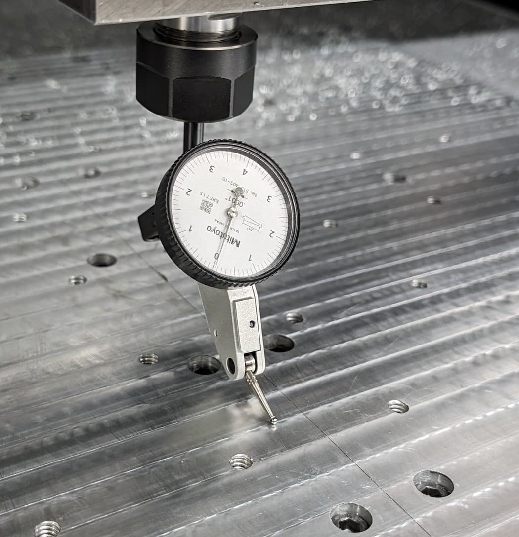
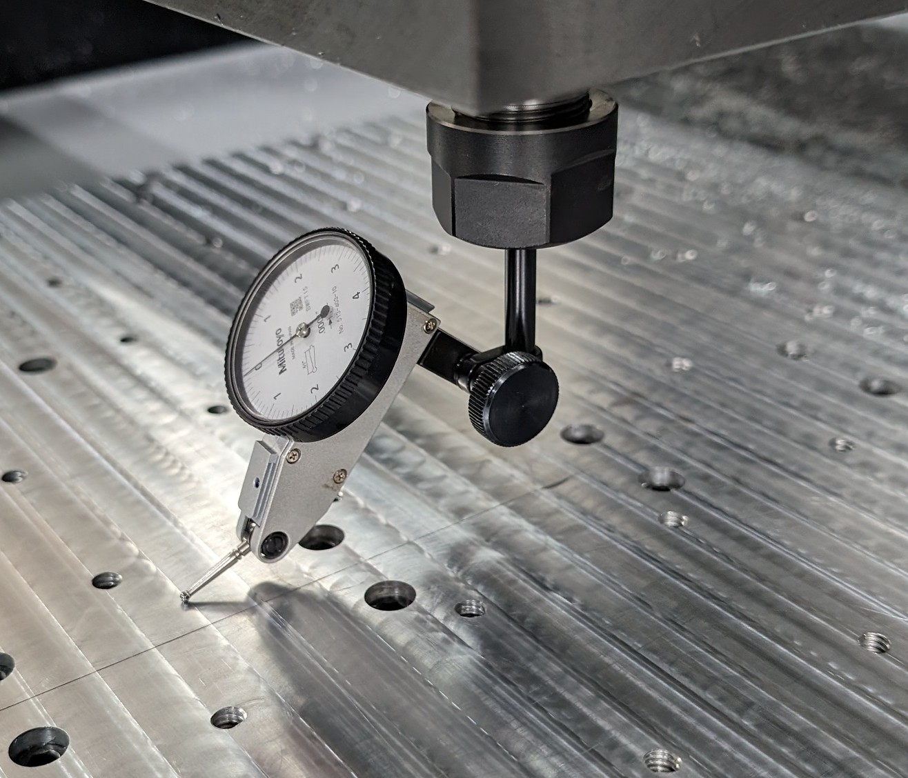
Working on it now. This is current set up and it does show high in back by about .005. which makes the step in base plate make sense. Will update on results. Thanks!
Skip is a wealth of knowledge. We all appreciate his wisdom. He has helped several of us. The larger you can sing while tramming the better off the machine will be. I swung the indicator over a 10" diameter and got it in to .001". the x axis direction was easy to shim and adjust. I found that the 3 bolts on the bottom of the casting were issues for the y axis. The center bolt could be over/under tightened and i could move the indicator .002". The center bolt will cause you fits. tighten up the 2 outer bolts first then tighten the center until you hit 0. I cut for 3 weeks and went back and checked and I’m still in good shape. good luck!
I am curious about the belt drive. Only reason for the belt drive is gear ratio (RPM) ? Would think direct drive would be better unless the spindle lacks some range of RPMs.
Torque at low range. I would rather break a belt than a spindle. Don’t need 15K rpms to cut steel. I cut a lot of plastic and could use a little more but 100 ipm limits me. Not sure of the pulley sizes on the motor and spindle but you could find the torque curve of the spindle and do a little math to find the sweet spot on the rpm’s.
Figure its something to do with that… plus the machine is not really built for much more added torque.
Think I have it dialed in as much as its going to get. Appreciate all the help. Was able to get front to back/ side to side/ tilt, and spindle all less than .001. Time to see if that translates to a good part. Need to run an easy program of a few features that are easily checked against. Time for the 360 learning curve. I have the 2d stuff down but the multi axis/ tool paths will be new. Here’s to good cutting.
Awesome! That should be a pretty solid starting point. Let the chips fly and see how it turns out.
Just wanted to chip in and thank Skip for his post above. I was able to get nod/tilt trammed in to 0.0005" deviation using a combination of the SST tram tool, set screw mod, shim stock between the spindle and carrier, and measured torque on the bolts.
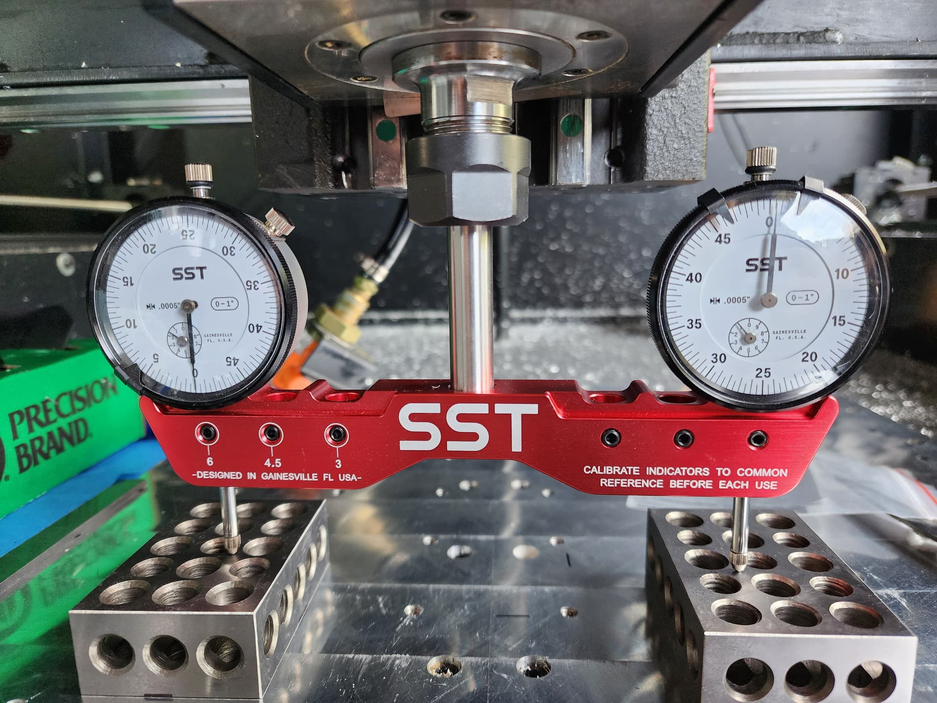
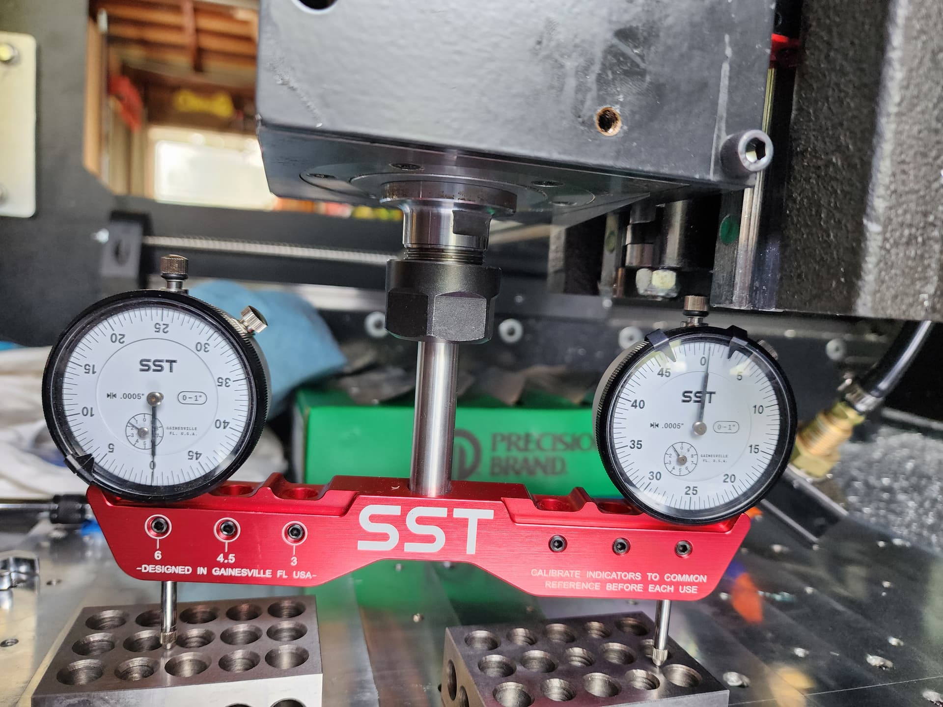
That is the proper way to accomplish this. With the set screw mod, you can dial it in perfectly.