So I was running through all the fine tuning steps tonight. Knocked out the travel compensation numbers really easily. X and Y were perfect right out of the gate and Z needed a 0.0005 correction.
I checked the z axis alignment per the @langmuirsystems video here
I was reading 1.5 thousandths deviation in the nod direction (front to back) over 3", totally fine for my needs. The tilt (left to right) alignment was 7 thousandths out over the 3" distance though. The video does really address the shimming process for this direction so I was curious if someone else has figured that out?
My thought was to add a shim in the upper position on one side of the carriage but wont this cause me to need to reshim the lower positions as well? Just trying to avoid chasing my tail as much as I can before I start doing the trial and error process here lol.
So the short answer, is yes you can shim between the upper bearings and the carriage as needed to correct the Z alignment error in the tilt direction.
However, we inspect every single X axis carriage and that includes the perpendicularity of the upper bearing mount surface to the z axis linear rail reference edge. If you kept your inspection tag, the measured value will be on there (should be less than .002" error which is measured over 6"). This is the only dimension that will materially affect the alignment of the Z axis in the tilt direction.
Before proceeding to adding shims to correct. I encourage you to check a few things. First make sure that your 1-2-3 block is actually resting squarely on the baseplate. Do this by first sweeping the top surface of the block in the X direction with the indicator to make sure you show 0 indicator movement. If you see indicator movement there, then the vertical surface of the 1-2-3 block is not perpendicular to the XY plane. This will obviously throw off your measurement.
If that checks out, and you are still seeing .007" over 3" inches. I recommend making sure that the upper bearings are in intimate contact with the mounting surface on the carriage. Consider breaking loose the bolts that secure the lower bearing mount, and then re-torquing the bolts that secure the upper bearings to confirm that they are in intimate contact.
If you do that and still see the .007" error, id recommend sliding the upper bearings out of the way and inspecting the mating surface for any burrs or defects that would prevent intimate contact. Not likely to be the case, but worth ruling out.
One last thing, make sure you have the 2"x3" face of the 1-2-3 block oriented parallel to the X axis when sweeping up and down the edge to check Z alignment in the tilt direction.
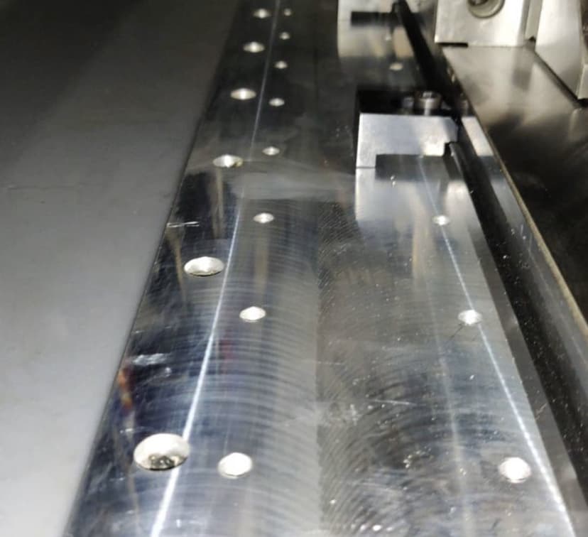
Edit: I took a second look at this picture that you shared with us on Instagram (hope you don’t mind that i’m posting here). From what i can tell there is very minimal ‘step’ between these passes which indicates good tram and by extension, good z axis alignment in the tilt direction. If your tilt was off by .007", you would expect there to be close to a .007" step between those two passes which doesn’t appear to be the case.
3 Likes
So I just double checked the inspection tag, -.001 nod and -.002 tilt. I will double check the upper bearing contact this afternoon and see what I find, Im pretty confident they were tight as I used a quick grip clamp to hold the carriage to them when I torqued everything down but stuff happens and maybe I missed something there.
I dont mind you sharing the pictures at all. A little more background on them as well, this is on the left hand side of my baseplate, as I traveled to the right I was starting to see some small steps, roughly .001 to .002 per pass. This really didn’t start until midway through the righthand baseplate section. So maybe I need to just take another small pass off the baseplate by running the passes in the X direction instead of the Y? I appreciate the response and I have no doubt I can get it dialed in with a little time. Ill run through it all with a fine tooth comb today and report back
@Arcworxs_LLC Thanks for all the info it’s super helpful. The fact that you have good out of the box tram with the large width fly cutter passes in the Y direction (step over is around 2") tells us that your Z-axis alignment in that direction should also be good. The first thing I would check is what @langmuir-daniel said which is repeating the measurement but making sure that your 123 block top surface is level to the XY plane. To do this, orient the 123 block so that the 2" length is running parallel to the X axis and the 3" length is running along the Z-axis. Then, use your indicator and sweep the top surface of the block and make sure that this is completely flat. Then repeat your measurement by sweeping up the block edge on the left or right side.
1 Like
Just got done running through everything again and its looking like I must have had something weird going on with the 123 blocks I was using. I started out really cleaning them well with brake clean and a rag. Ran the dial indicator across the top plane and saw .0005" of error over the 2" span. I also ran the indicator across the entire width of the baseplate and only saw 0.007" of error across the whole baseplate. So the tram checked out there.
I then rand the indicator down the z axis faces on the 123 block in 4 different spots on the table, all locations measured in a .002" of error or less. Z axis alignment looks to be good there as well. As another check I also ran the z axis alignment tests in the top, middle, and lower range of the z axis travel range. All three areas had similar measurements. So Im guessing I must have had some form of contaminant on the 123 block the first time I was testing.
I will say I am super impressed with how accurate this machine is straight out of the box as far as the alignment goes. For there being so many variables and opportunities for user error it really speaks to the quality of design put into the machine by the langmuir team. Super excited to finally have the machine 100% calibrated and start running parts
2 Likes
@Arcworxs_LLC Thanks for circling back with the follow-up and glad you were able to double check the measurement with success…Next stop; part pictures!