So I am late in the order line-up…I was hemming then hawing as the dates slid away , then went from hell no to what the hell. Point being I have skin in the game for these questions
Question on the Z axis - I have read through the comments, but I don’t believe Langmuir has answered this directly.
Some of the Langmuir site information points to being able to mechanically adjust the “z” for 2", but then there is the “Bonus” animation showing what looks like a 2" automated spindle retract.
I am assuming it is a mechanical adjustment, but knowing for sure would be nice.
Also, please let us know how these adjust and if there is a range of adjustments or if it is just 0" , +2"
1 Like
Hi there, yes the 2" of ‘bonus travel’ is merely mechanical/manual adjustment. You an adjust to any height between 0 and 2". Normally when we are hogging we like to retract the spindle as much as possible since this is where its dynamically most stiff. For work that requires cutting low (close to the baseplate with small end mills) we’ll retract the spindle. Our guess is that 90% of projects that folks will do will be retracted.
1 Like
Thank you
You say retract in two instances , when you say retract are you meaning pulled up in the Z “+2” or down in the Z “0”. I would assume retracted is up and extended is down.
Are you saying it is dynamically more stiff in the +2" retracted position?
Also , is the z axis linearity / concentricity going to remain intact?
Will the spindle need to be trammed after every adjustment?
Thanks,
Yes retract means +2" in Z axis.
Yes, deflection as measured at the cutting tool will be less with the spindle retracted as compared to it being extended.
Yes, alignments are maintained. The spindle does not require re-tramming between adjustments.
Anyone have a drawing showing this adjustment area on the z-axis? Or ideally video or procedure? Appreciate any help! I am about to deck my plate for the first time and want to make sure my z-axis is as high as possible in conjunction with the new extension and fly cutter.
Thanks,
John
Thanks!
In the video, he shows adding two buttow head 1/4" cap screws back through the front of the carriage casting and in to the mounting plate shown here:
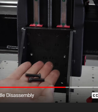
However, my plate ( below) does not have these holes. Anyone know if this is “new” style or ommission of process?
Thanks!
John
That doesnt look right. Its entirely possible those didnt get drilled and tapped at the factory. Mine had those holes. However, my machine may be older or a different version from yours. Id send the Langmuir guys a tech support ticket and send that picture with it. Their Z axis stuff was a shitshow for a while due to some of the assembly guys skipping QA. I had a few little things that were screwed up when I was building my MR1, but the customer service team got everything fixed quickly.
1 Like
I did just what you described…I’m guessing skipped op and I’m playing disassembly/re-assembly. Will report back!
1 Like
Well, update time 
First off, Jake and the crew at Langmuir are great customer service reps. They respond to issues in a positive and helpful way. To me, this is extremely important.
That being said, it was not fun replacing the main plate lol. It did not have the holes as shown and it was a skipped op. So, they sent me another one. Spacing on this one didn’t align correctly and at this point we were kind of off in the weeds for more field repair. They sent me a new spindle and z assmbly. Working through that now…it’s been a long ride!
2 Likes

