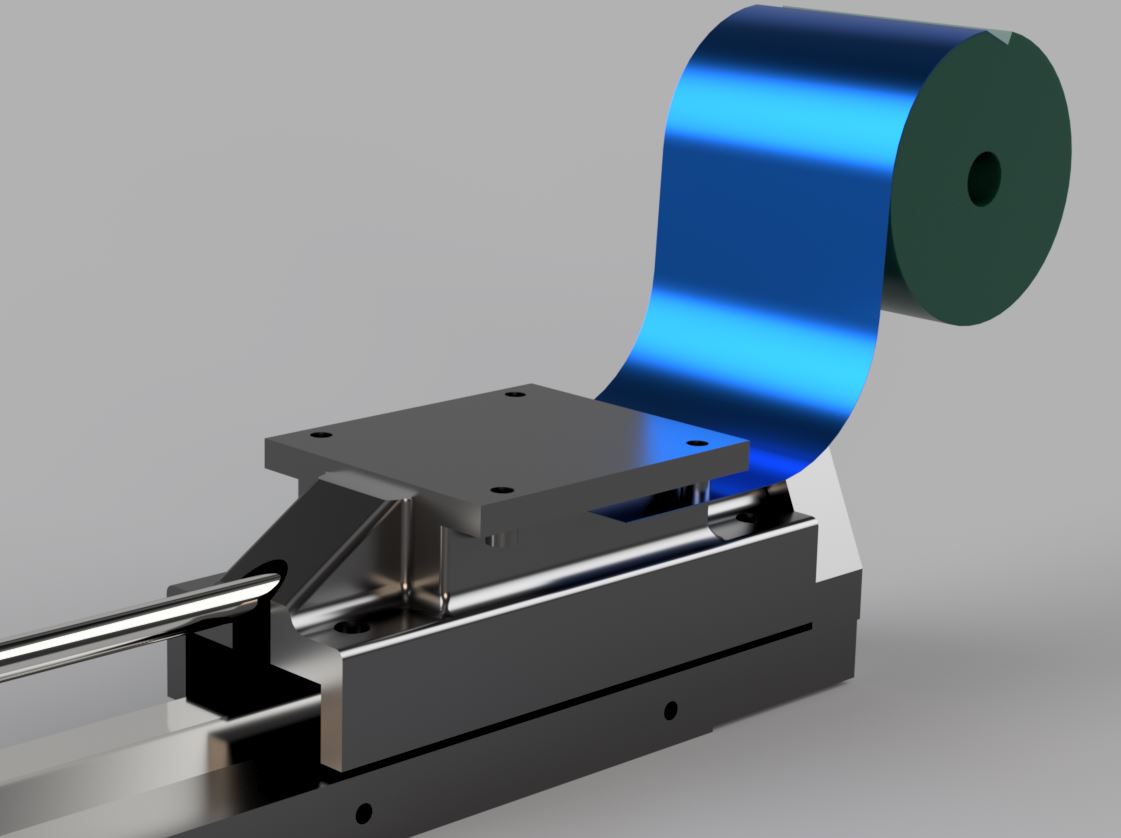
There are a few Y rail cover options, and I’m wondering what the general consensus is about which might be the best option. I was initially thinking in terms of blocking 100% of the chips from reaching the Y ballscrews and linear rails, but maybe the shield kit by @AE95 with 90% blockage is more than sufficient. Like he said, sometimes simple is better. The @amosdudley Y rail cover idea also looks like it would be a good option. I would consider both of these options, and I also have another idea that I was thinking about making which involves the use of a 4" wide 0.01" thick spring steel coil with the goal of blocking 100% of chips and cutting fluid. I began sketching the idea in CAD and there is just enough clearance so that the side panels of the rail cover could be stationary with only the spring steel coil on top needing to move with the Y axis. Also, with this option I was thinking that the @amosdudley cover idea would be better suited for the X axis. Would be nice to have both the X and Y axes covered. If there is enough interest in this Y cover idea I could make a prototype.
This seems like an OK strategy to me, although in my experience chips are flung at the sides of the rails and screws, not the top. You could angle it, but then you wouldn’t get top coverage.
To me, the lower X axis rail actually seems like a better candidate for this kind of unidirectional shield, since the X screw and top rail are occluded by the gantry beam, and rarely see debris.
I made some progress on accordion covers for my Y axis here, btw:
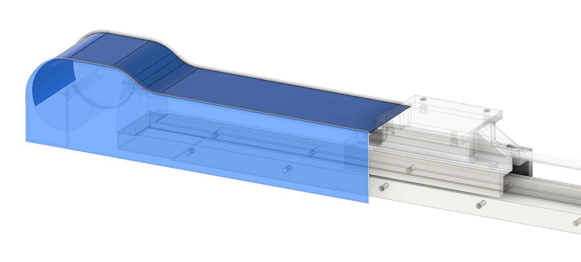
Good work @amosdudley on your accordion style Y rail covers! Just a point of clarification on the spring steel coil approach - there would be 3D printed sides to completely seal the ballscrew and rails. Here is a previous sketch that shows side covers. These are just rough sketches. My only concern with the accordion style covers was chip buildup on top of the covers that would prevent them from completely collapsing, but maybe that wouldn’t be an issue. Anyways, great work on your entire build. I found your epoxy granite and creative modifications to be inspiring.
One thing to keep in mind is maintenance. Since there is no automatic oiler, you will want the cover to be easy to remove to clean and oil the way and lead screws or add oiler ports that feed from outside the covers.
When I built my first shield I was surprised at how much it stopped. The biggest weakness is a cut along the front of the material head to the left side. This throws chip more forward and has the most chip that make it in front of the shield. I am working on a multi stage setup to provide better coverage to the front.
I have looked at marking complete inclosed shields with the biggest issue being seals between the panels. Have reached a bunch of design but a lot of it comes down to the cost to make compared to what people are willing to spend for said shields/covers.
I hope more people will chime in?
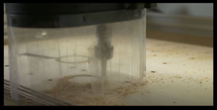
I look forward to seeing your multi-stage setup. Another question I’ve been wrestling with is, when all is said and done, are shields/covers really necessary? Langmuir has stated that in all their testing they saw no problems running with the stock setup. Perhaps a more strategic approach to improving protection would be more robust wipers for all the rails and ballscrews. Another approach I’ve also been thinking about is a type of shoe around the base of the spindle that would work to block the chips right at the source, something similar to wood-working cnc machines like in this picuture, but modified without dust collector and maybe wider and longer. Something along these lines would help all 3 axes. Also, for the Z axis, I was thinking a relatively simple 3D printed flexible accordion style cover might work, but I haven’t had time to sketch that out yet.
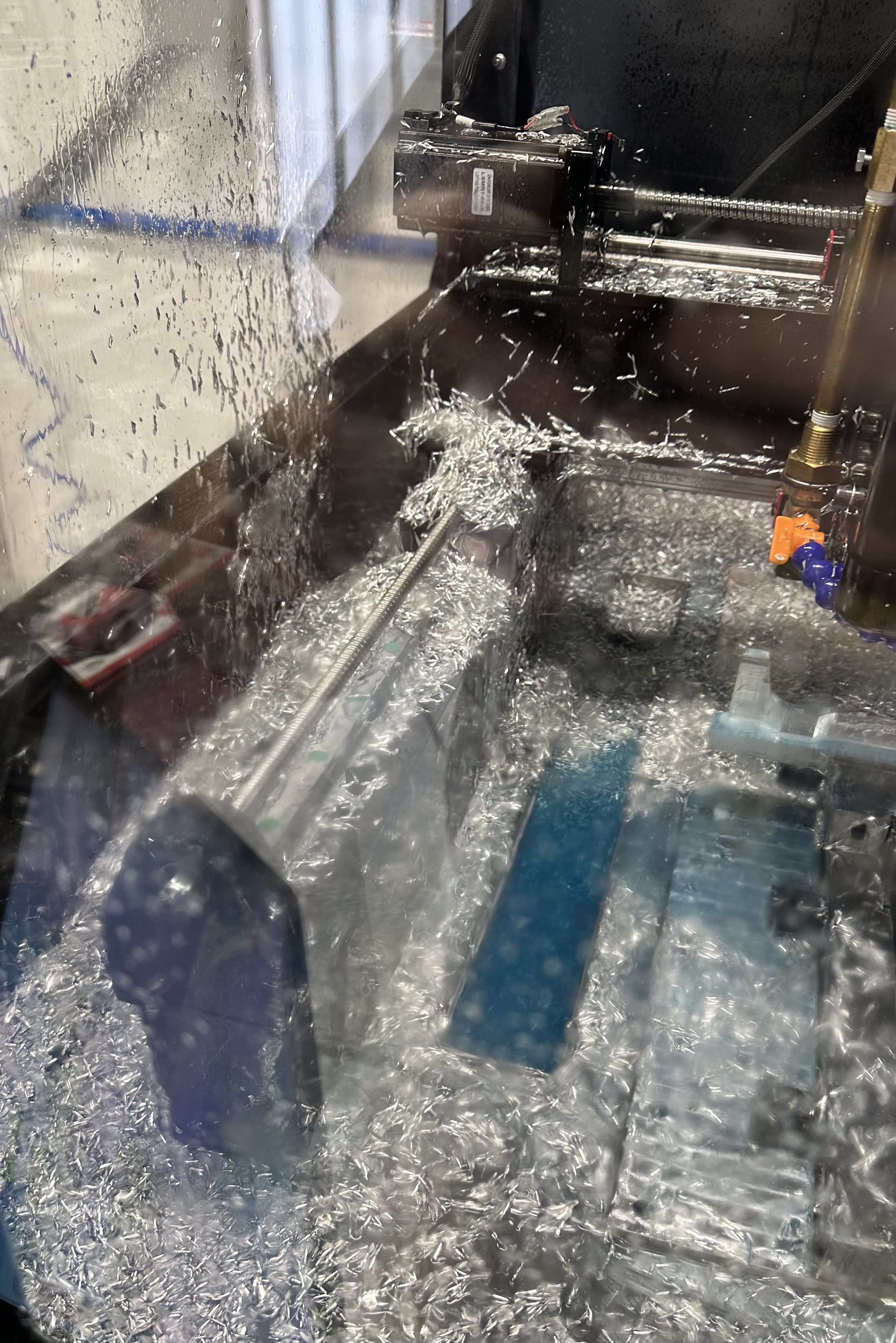
I also think the linear rails and lead screws will be fine, and can handle getting chips on them. However the issue I quickly ran into is that during large hog out ops the chips quickly build up around the Y carriages and this did cause issue when the carriage tried to home after the completion of the op.
Hi there,
I made some from aluminum flashing and 3D printing. Here’s a video showing it off. I’m almost done with the full setup including X axis cover as well. I’ll start a new post on the forum when its finished and will also post free STL files for anyone who wants to print their own. Cheers

I laser cut some side shields to at least help a little. Also made a few dust/chip shields just to help reduce chips/dust from flying everywhere…
2:37am Studios on Instagram: "#mr1 overview. Still working on getting it up and running. #steel #aluminum #acrylic #fabrication #custom #mods" more videos in there… right click/open in new tab if you don’t have IG… should play
Those look great. I followed!
Hi Everyone,
You can grab the STL files from here if interested. Cheers.
https://www.pithybuilds.com/?page_id=61
Nice job. I bet it wouldn’t take much modification to do the X rail as well. Maybe shorter height and one of each side of the head. Would just have to figure out how to attach it each side of the head and each end of the rail.
Yep! STL files contain the X rail.
It will be interesting to see how these hold up. I’ll be cutting parts in the next few days so we’ll see how it goes. It’s possible that dry cutting fluid could gum up the covers but we’ll see.
Really like your solution. Also your YouTube channel is great, subscribed.
In looking at your STL files, I was trying to determine the quantity of each part to print and I’m not sure on every part, which are separate parts vs duplicates of the same part. Do you have a breakdown of the quantities needed for each? Thanks! Again, great work on this.
I’m working on some rubber sheets like a knee mill uses. Fingers crossed…
I based my design off of yours #PithyBuilds, and everything is 3D printable. I am uploading it to the Facebook group for anyone that wants it.
Hi Everyone,
I made V2 of my rail covers. They are now fully 3D Printable. I’m offering the .step, .stl, and pdf for sale on my website if anyone is interested.
And a video about it. Thanks!
This looks like a solid design. Have you had any issues with hot steel chips melting and damaging covers?
Hi Alex, I haven’t had any issues but I use coolant for everything. It takes a temp of 158°F–176°F to soften PETG. Chips do reach higher temps but cool pretty quickly. On my old design I did have some parts that were full PETG and they never showed any signs of heat stress. I only machine aluminum.
Looks like a nice improvement! I like how you increased the rigidity of each segment.