Is cut square now, adjusting limit switches is to get square cuts .If dimensions are too big you need to measure what torch kerf width is and input in cam tool. As consumables wear the kerf width will get wider .
1 Like
No sir, adjustments did not help, I did measure kerf and that was very close, I put this in a post earlier if you don’t mind checking.
This was a brand new 45 amp SYNC hypertherm consumable.
Sheetcam has the correct kerf per material thickness.
do you get the same result from cutting on all parts of the table? have you tested a cut in each corner of the table? if you get different results in different parts of the table then you have a hardware issue. if you get identical results on all parts of the table then it’s more likely a software issue. not a perfect diagnostic tool but it might yield a helpful result.
2 Likes
Good call, aside the large plates, I’ve cut everything from middle to the computer side. I’ll try an upper corner today. I ran an old file that was spot on 10” OD from before that is now NOT 10” OD. But I’ll check again today. Thank you
2 Likes
Ok, so I recut the same file with both 45 amp and 30-45 amp time cut low speed nozzles at the home position corner area.
Same problem this file is coming up almost exactly 1/16” short from 10”, I double checked the file in sheetcam, was spot on 10”.
Seems to be mechanical issue as you and Richard have stated, sounds NOT to be a file problem .
I changed the kerf as well to see if that was off and same thing still off. I have cut 4 of these parts and all seem to be consistently off.
I did recheck squareness yesterday on top of the water trays and was a 1/16” out from being square, seems fine to me at almost 10 feet across .
Gents what else can I do or what else could be wrong???
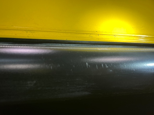
I do want to note something that stood out on the X axis in this picture… there is a distinct line from the bearing all the way down the X
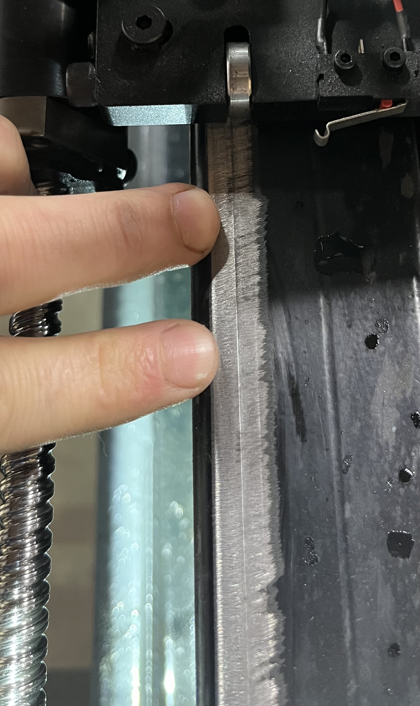
sam, as i recall from another post, you have had issues since this summer with binding and accuracy. the paint you ground off your frame in that picture I think was one of your bandaids to alleviate one of these issues. the paint grinding and groove you are referring to in that picture is evidence that you may have set your bearings a little too tight. when you ajust your bearings it should just barely take the play out and absolutely no tighter. if you disconnect the assembly from the motors/screws it should glide across the rail easily. based on the groove and the paint removal, im guessing that yours would not have glided along the rail very easily. this however does not solve your cutting accuracy issue.
it’s time for tough love Sam. having looked at many of your posts regarding your machine issues, i am fairly confident in saying you have screwed up your machine during assembly somewhere. 1 or many adjustments are not right. the squareness of your water tables is inconsequential. it’s everything else that needs to be checked and maybe even partially disassembled to correct.
it is very unlikely (not impossible) that this is an issue with manufacturing. i doubt that any more time spent on the phone with customer service will correct your issues. im not even convinced that the bearings you replaced were the issue. something is out of square or improperly adjusted and your binding issue and this cutting issue may even be connected.
I wish i could just stop by your garage and help your diagnos your issue. if you were in Utah I honestly would. i have felt your frustration. but my gut says you’re machine is at best a parallelogram and not square. i have several other suspicions about parameters that need to be checked but the truth is that things like grinding paint off is indicative of your problem but was not your solution.
i have had my own share of issues up front and every issue I encountered was correlated with someing that was improperly adjusted or out of square. it was always me.
had the same issues with 3d printers. we have multiple 3d printers in our family and we saw similar issues with prints coming out poorly on 2 different machines. on one the rollers were too tight against the rails on the other they were too loose. your table is the same. binding is caused by your fit being too tight, too loose, and out of square. if your cuts are consistent but out of square it because your table is out of square if your cuts are not consistent it’s because there is play in the machine somewhere. if they are inconsistent and out of square then you likely have more than one issue to deal with. if they are square and consistent then it’s your settings. if your cuts were but now not good then it’s likely consumables. bad consumables could easily throw your dimensions off by .04"
if the problem appears to be witchcraft then it’s the limit switches.
my leading suspicions are the table is out of square which could be your rails or the table frame and your rollers and rails are not properly ajusted. please don’t use your grinder anymore to solve issues i promise there is a more practical solution too your problem.
5 Likes
![]()
![]()
I have to admit, that was funny to read but I feel you are correct as well as the other members here. Upon assembly when I first got the machine going I smashed my limit switches to oblivion…… with the link Langmuir had in case this happen, I ended up buying the limit switches with the roller on the end, that being said when Richard said to get both sides equal I had a little bit of a time figuring that out because my original switch’s got smashed.
The assembly guide for me was difficult in some areas because everyone has a different feel for things, your hand tension may be different than mine or another member.
I will say that you offering to come to my shop goes a long way with me, I really appreciate that and I mean it!!! I’m on the far center of the East coast so I’m a very long way from Utah.
So what parts prices do you recommend starting with and or taking apart (I am forever dredding taking off the water table) , but if it’s not right, it’s not right. I will take all the tough love I can get from you or any other member here. This is how we learn to help each other fix things and get as many as possible cutting right with our machines.
I also feel your correct on it being a parallelogram 1 side was consistent within a few thousandths and the other side was about .005 - .010 bigger but consistent as well. So that makes sense.
Please let me know what you think is best for adjusting what or taking apart pieces.
Thank you so much
3 Likes
When adjusting the Y axis limit switches, the left and right switch won’t necessarily be even adjustment with one another to get gantry square with table. Cut out a square and see how much out the dimension is from side to side and adjust limit switch to get a square cut.
3 Likes
I cut out 8 3x3 squares today and did some changes.
Richard, I adjusted the limit switches today to 1.700” on both sides to start off at a solid number.
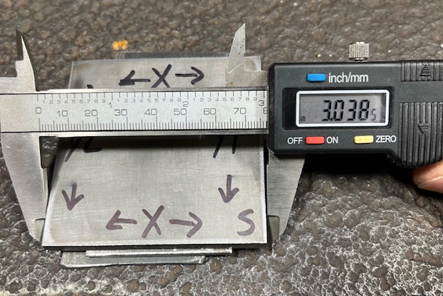
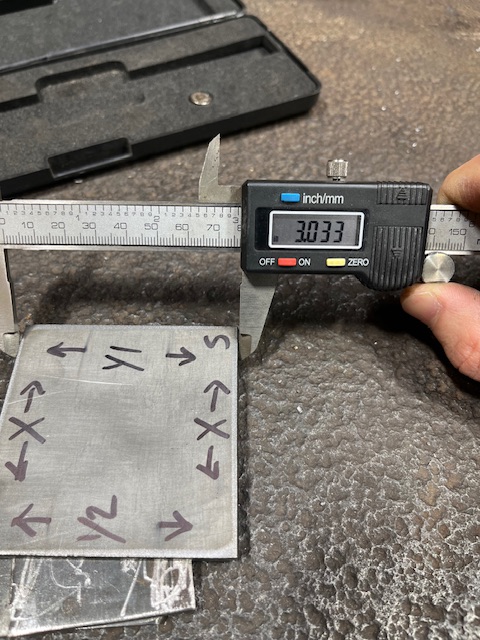
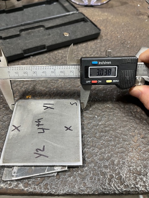
Upon cutting the 1st square I got about a .005” difference from 1 end to the other and roughly the same on the other side. I took some pics to show, (S) is start point then showing X,Y direction. I was still out of square measuring from corner to corner and the opposite corners.
I then took the difference ( from 1.700” to 1.720”) and adjusted 1 Y axis and cut another square and came up with the same numbers.
I then turned back the same Y axis to 1.695” and cut another square, same identical thing.
If adjusting the Y axis doesn’t change the part measurement what else can I do.
Also, my part drawn to 3”x3” on F360 still came up .030” bigger no matter what. I changed my program again to 2.970 and the part was within a few thousandths of being spot on 3”. That is a corruption between computer to machine. I did get smoother stirations on the Y side of the cuts than the X sides of that is something to consider…
Pics
Set at both Y axis at 1.700”

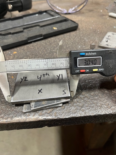
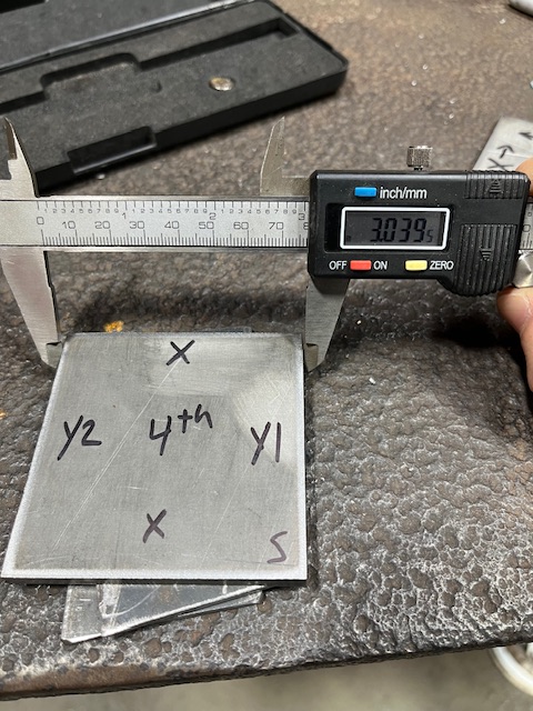
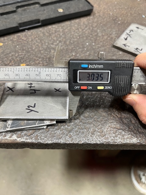
2nd set (4th)
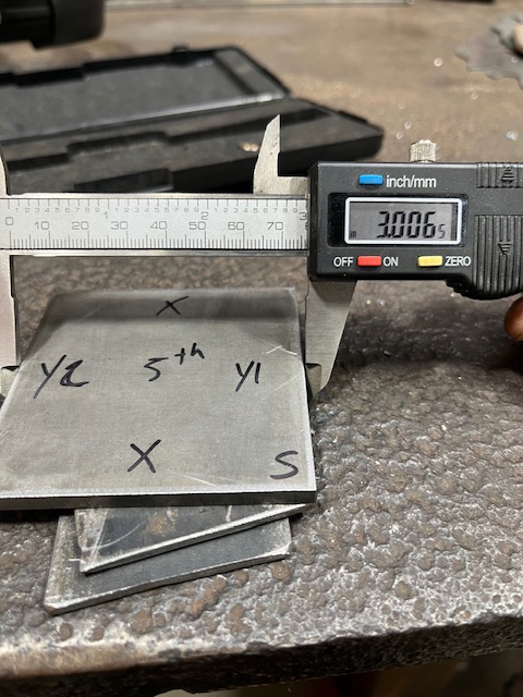
After changing Y axis to 1.720”
3rd set (5th)
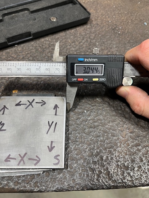
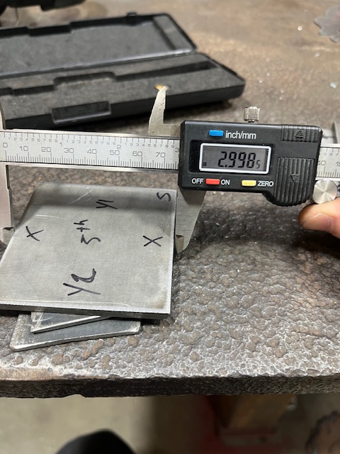
Changed program for square to 2.970”
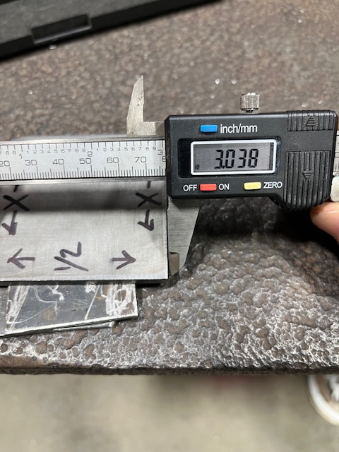
Y axis set to 1.695”
4th measurement taking diagonally from corner to corner and opposing side
On 2.970 part
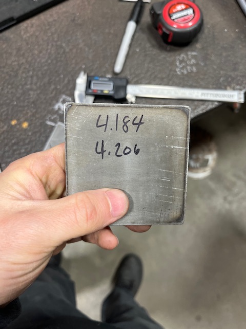
That .011 your out of sq on the diagonals
I don’t think that’s to shabby. A rough spot could be part of it.
I would have to check to see if I am any closer
1 Like
For being a test square it’s not bad, but multiply that on a large part like my 12”x22” pan bottoms and that number grows significantly, hence the 1/8” out of square.
2 Likes
sam, ihave been looking at my table to find a creative way to check for square without taking things apart and its not a simple task in afraid but one thing you can do without disassembly is check your rails for parallel. get a couple of 5 to 6ft pieces of square tube and run them from the ground up past your outer rails on each side of the table. zip tie the tubing to your rails then plumb each side and double check that the measurement between the two pieces of tubing at the top and bottom are exactly the same. then write that number down. do that at each mount point and see where you’re at for parallel.
I will see what I can do this week to check that.
I did check level across my X yesterday and did find that it was not EXACTLY level, which before I was certain was, but this was before adding water. I was indeed not level on leg was 1-2 turns shy to be level , as was the opposite end. Across the Y was level after I adjusted the X level. Not sure if this means anything but I did check this as well. I haven’t cut anything else since the test squares.
1 Like
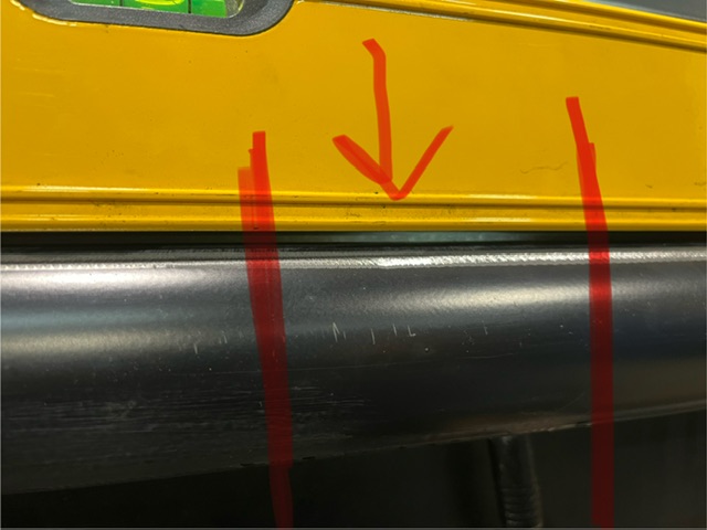
Update as of today.
My Y2 rail has a bow in the middle (see pic). I put my 6’ level in it and noticed there was a decent gap, about .065-.070”, I used feeler gauges to check this , the other side was much much less of a gap. So I decided to recheck the parallel for the Y axis’s. Low and behold they were not the recommended gap of 1.25” in between the rail and bed…… so I will be adjusting this and will get these numbers where they need to be.
Not sure how but obviously I did not measure correctly when I installed the rails….
So for now this is where I am at.
2 Likes
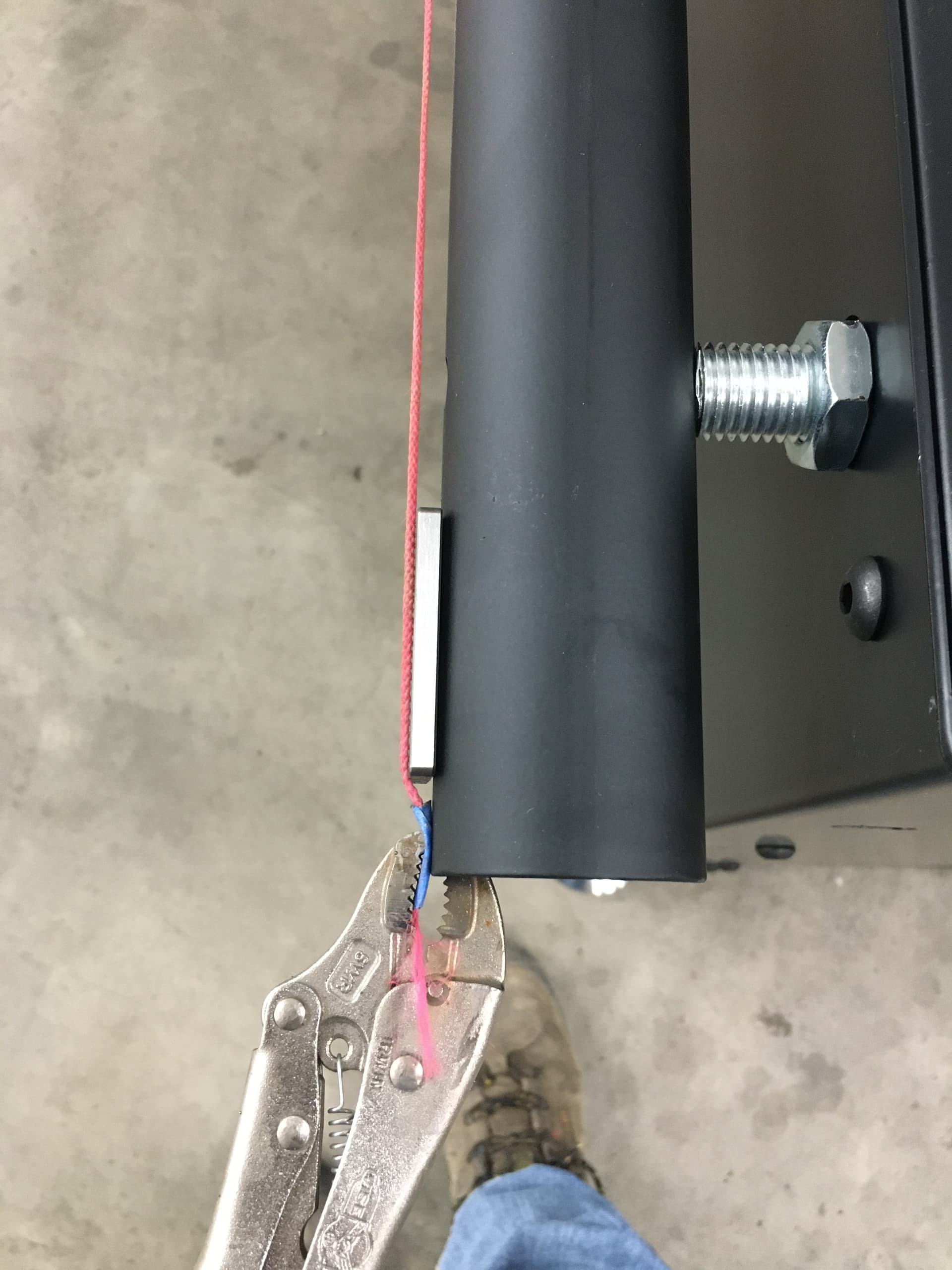
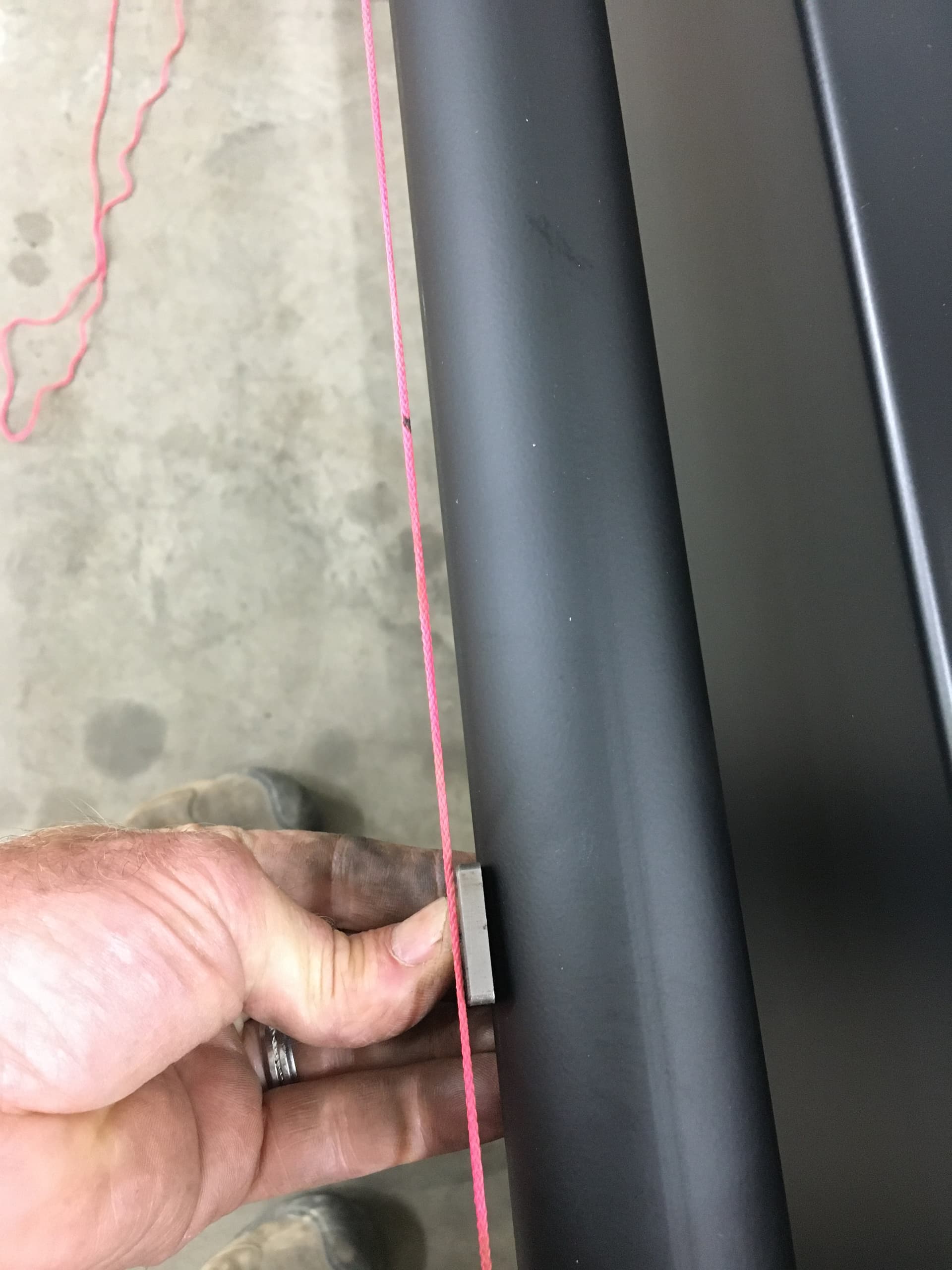
When I installed my Y access rails I used a string to make sure they were straight from one end to the other. Pictures show how I did it with string.
Clamp string at each end, get 3 shims all the same thickness put one at each end and use the third to measure with. Adjust the nuts in and out until your shim just touches the string.
you should be able to get them with in .015".

4 Likes
That’s a good trick, reminds me of a construction tip when building houses/garages or buildings.
1 Like
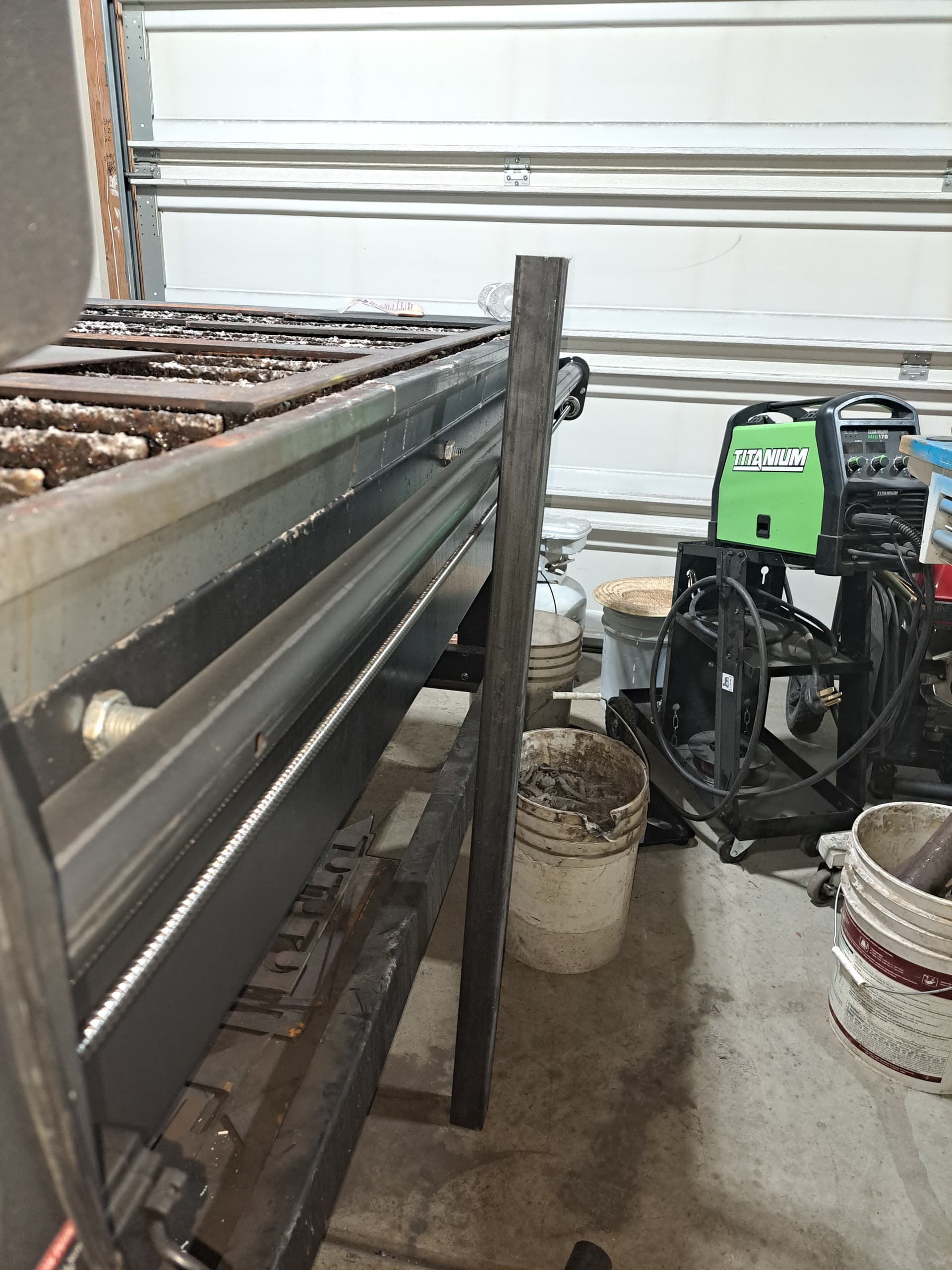
So my wife and I spent from 1:30-7:30 yesterday working on my machine. We started with checking the 1.25” gap on the Y axis. I had that measurement on one side and not the other from when I previously put the machine together. So we worked on that and this time got the numbers right, then we checked the distance in between the rollers, added the 1.75 and made both ends parallel within 1/32” on both ends, we ended up having to loosen the rail and rod mount plate because it was putting the rail in a bind. Once we got that right we went to the back to check the rod tension and completely readjusted those. Took both ends loose and started from the beginning. Once we had the tension correct (best we feel was correct) with about 3/8” of “play”. We then went to the X axis and did the same. We readjusted the rod tension as well and then we re-trammed the Z, we took the torch off and the clamping brackets. From how I initially set my Z up I do believe I have a bad bearing from being misaligned and to tight and or not set correctly. We spent some time getting that square to the slats and then redid the adjustment for the bearings. I will say this, the groove/line that the bearing had cut into the gantry tube that I showed in a previous post was NOT in the same position as before, now the bearing rides in the middle of that cut/groove. So yes, from I what I had thought I had gotten everything right from initial install was not done correctly……… hence the trouble I’ve been having with binding and not cutting square.
Once we put everything back together and double/triple checked things I went ahead and tested the X,Y and Z movement manually first, once that seemed fine I ran the Break in program, that was a success, no binding and loud chattering, then we went for a test square. Same material at the same spot with the same program. The square was still .030”-.040” big than the 3” I programmed in F360. Still leads me to believe that’s a programming issue. I then moved the plate to a different spot on the bed where I have t cut anything and recut a square, this time the measurement was more consistent on all sides within maybe .005-.007”. I can live with that to an extent.
BUT I now have a bevel on 3 of the 4 sides, could this be related to torch height or cut speed or air pressure???
I would start with cut height.
Here is how cut height effects bevel https://images.app.goo.gl/CYA1vcoSgtGy3GG57
2 Likes
Knick thank you, I will make some adjustments next time I cut .
1 Like