Hello the title of the thread is copied from the spec’s page on the website. Im wondering how that has worked for you, who are using this machine. I realize the Z travel is 6.1" and you can get another 2" of passive clerance. Ive watched some videos of the machine and see most of the time the tooling probe is in the right fromt corner of the bed.
If you had a part in the vice that was 6" tall and had to mill on the front of that part how much clerance is there from the bridge to the center of the spindle. Or if you had that same 6" part in the vice and needed to do a tool change would you simply have the probe located in a different place, like the rear corner of the bed?
Im thinking the practicle Z height is 5.5" as your max off the bed, part plus tooling (vice etc.)
Am I correct here or missing something. And has that limited your experances with the machine.
Thanks for any input .
Mark
Clearance is one thing, being able to move the tool around and changing your CAM to not add tool paths that would cause the machine to post a travel beyond limits error is another and something to be aware of.
I’ve found the Z travel on my MR1 is one of the biggest downfalls of the design. Its essentially limited to large flat parts or small parts. It does what it does fairly well but I’d very highly recommend evaluating the type of work you want to do and work back to machine requirements instead of picking a machine and seeing what you can do with it.
So far I will say that with my use case I’ve only not been able to work something if Ive had to reach into something with a fairly long tool. Im also not making what would be considered tall parts.
Thank you for your thoughfull reply. I currently use a Grizzly G0704 CNC and only have a couple of jobs where the height/clerance woudl have been a problem and I think I probably could get around that with fixturing.
I really like the footprint and feedback Ive seen on youtube for the MR-1. Mine priced out today would be $8k plus shipping, for that money it would be hard to justify another $10~15K for a good used Tornach.
A low profile vacuum fixture on this machine could really be a nice setup. Will see what happens in the near future when the hobby crowd really gets the mods going. Im half way to my price goal and should be able to pull the trigger sometime next year.
Thanks ,Mark
One person on here built their table with a through hull in the center so that they could work on taller parts. It’s an interesting concept though likely reduces rigidity and damping.
For my work the lower Z hasn’t been a problem. Getting 1" more through risers isn’t too difficult either.
I’m still planning a 2.5” through hole in the center of the table plate for a 4th axis. Also making (6) 12” x 3.5” x .25 wall square tube uprights, significantly raising the Y rail plates to make room for ISO/BT30 tooling.
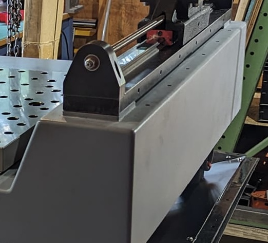
I’m having trouble envisioning where you will put the 6x 12” x 3.5” x 3.5” risers. Can you explain or share a picture? The only thing that I can see would be raising the Y rails by 12” which sounds much too high to me.
I’m not raising the rails 12”…more like 4.25-4.5”. The supplied Y axis rail mounts are about 7.5” x 2.75 x .120” wall thickness and they won’t be used.

Also increasing pan depth about 2” and surrounding the uprights on 3 sides with concrete similar to this EG custom build.
A 33” x 4” x .375” flat plate (not shown) will go on top of the uprights, likely anchor bolted to the concrete like the table plate.
Ah, I get it. This is much more of a redesign.
I saw a picture of your redesign and was supprised you werent inundated with questions on how you did all of that. Id like to see more of it if you care to share. Im not too worried about the tool change issue many have asked about, but a BT30 spindle would be pretty cool.
My work so far hasnt really required a tall part requirement and I do have a manual knee mill I could do the odd parts here and there. Also if your using a low profile vice that would limit how tall of a part you could effectivly hold and not get chatter.
Thanks for all the replys.
Mark
I haven’t done it…yet. I don’t have drawings since 99% of the design is in my head. It all has to be fabricated obviously and it’s very time consuming. You can see the amount of work and planning that went into AmosDudley’s build.
I don’t want to get into a lengthy explanation but will take pictures as I go and post them when I’m finished. It’s just going to take a while because I’m also trying to do it on a reasonable budget.
BTW, 2” of passive clearance is a much better description than 2” of “bonus travel”.
I am very new attempting to figure out since I don’t have any knowledge of how long the tools are vs. how much height remains between the clamped down object to “cut” and the ability to fit the gantry “over it” I did send a picture and request to the company but I want to double check somehow from other sources
We have these made from brass round bars at a shop for many years. Like a grampa shop where some of the work is done on manual machines.
The outside diameter is very close to the bars, we imagine cutting slugs on another machine to feed the gantry mill. The diameter and height of these is 1.5 x1.5 up to 3 inch by 3 inches.
If we can make appx 7 units per hour then this is in our range of production. We may make 500-1000 per year spread out over the year.

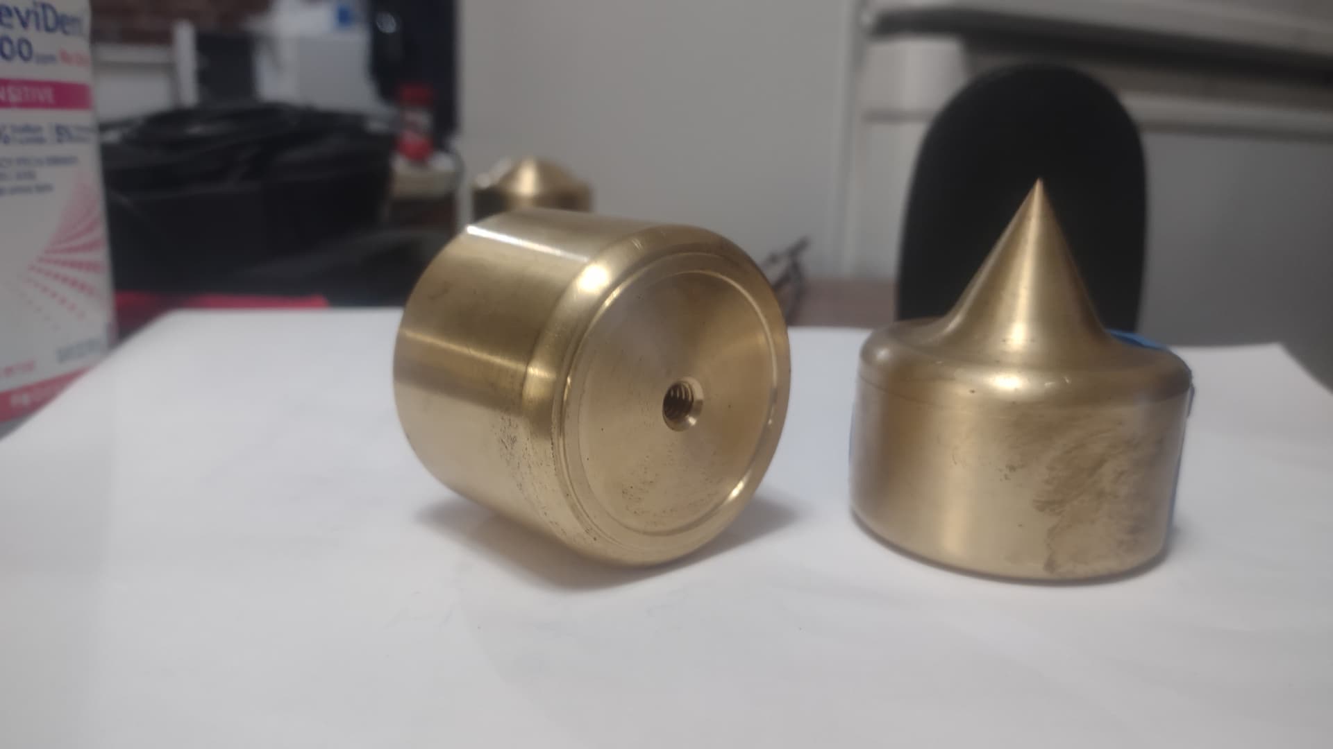
A CNC lathe would be the right tool. I don’t think it could be accomplished at the rate you need with the MR1.