First… thanks to everyone who have helped me so far. I was ready to bail on fusion 360 several times… I am a total newbie to autocad and am trying to self teach. My machine is scheduled to ship shortly and Im still not successful at getting a file all the way through the process
I have gone back to square one several times… deleting my cutter and starting fresh … using LM videos to take me step by step. It seemed to me all I got was toolpath and contour errors.
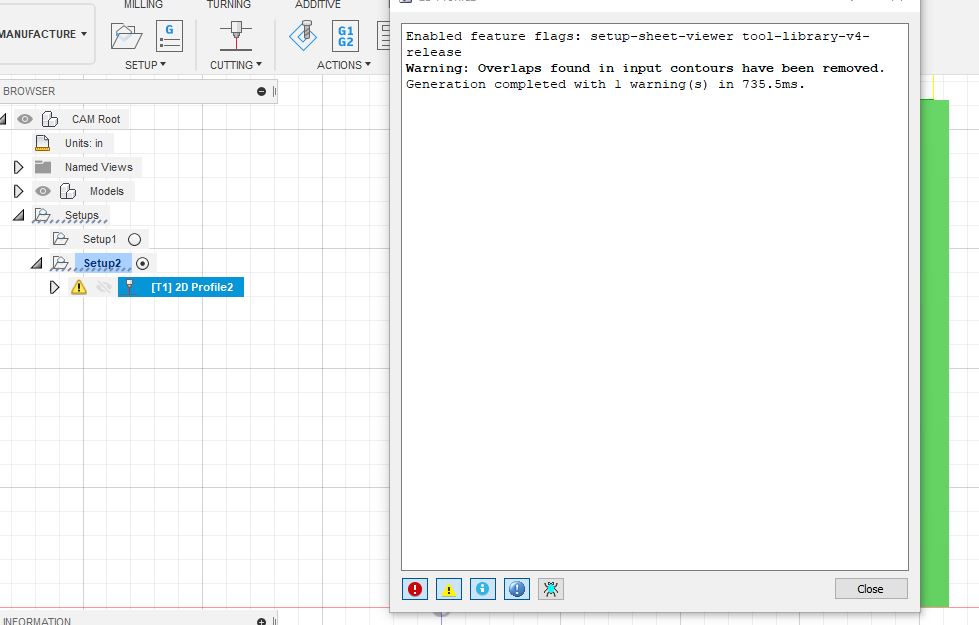
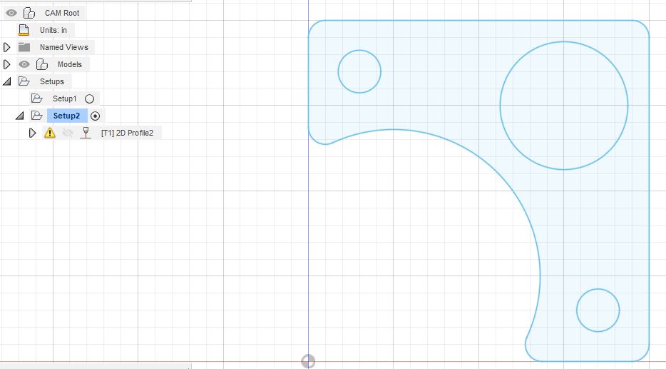
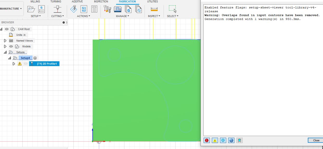
Today using a DXF from the site I tried for a simple rollbar gusset… everything seemed to be going fine… my cutter finally stopped giving me an error code… but now a contour code error…
When I google it I dont seem to find any answer that is useful
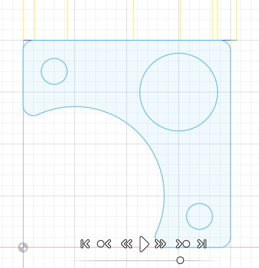
I saw the red direction cut path arrows in all the areas. My x/y was set correctly.
When I tried running it the error message displayed
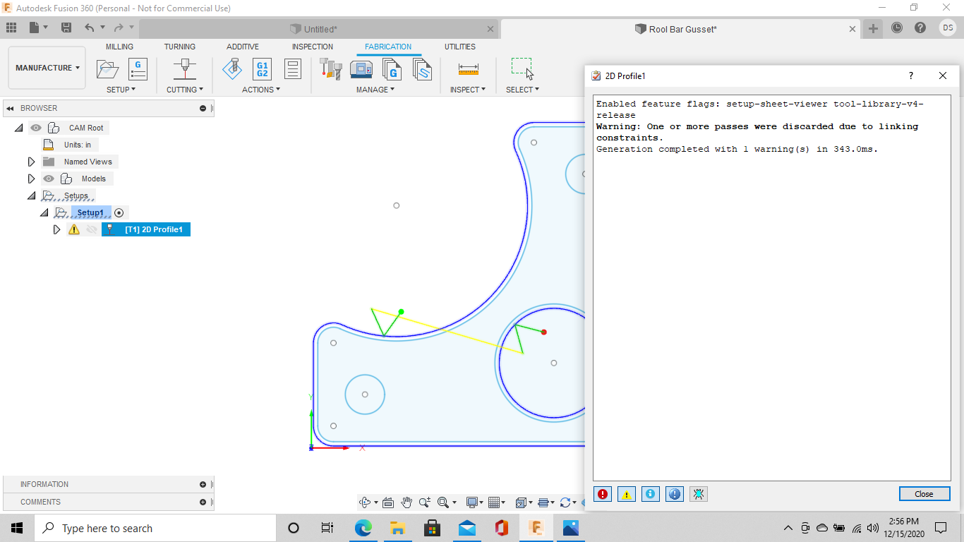
How did you resolve getting rid of it? If I understand you correctly you reset your lead in… what did you set your file to?.. and if so… why was the original file lead in wrong?
What he’s referring to is when the the lead in is set to a value that conflicts with the hole or cut path. For example, if you have a lead in that is .25" and you are cutting a hole that is .25", the lead in won’t work and will cause cut problems, and you’ll get a warning. In cases where I’m cutting lots of small holes, I’ll actually create a new cut profile for just those areas and set the lead in value differently - so my setup will have 2 cut profiles - one for the holes and one for the outline of the part.
Edit the 2d Profile settings and adjust lead in / lead out to fix that issue
…but that’s not the issue you are having…(yet)…
In your screen shot - you have 2 setups (setup1 and setup2) - you should only need one. There may be a cut profile in other one that is causing the overlap issue?
I tried that too but I can’t make it duplicate his exact error. I know you only need one setup but if you do end up with more then one accidently or for whatever reason it only allows you to highlight one at a time.
Did you modify the download at all or just used it as is?
Thank you gents…
I used the download from the site as is-no modifications… I picked the simplest one I thought there was. My thought process being it would reduce chances for errors… and if i can get over the hill on one… others will follow… no joy happened…
Ill go in… delete all and start fresh
baby steps
I am also going to address a separate issue and that is my computer… I am going to invest in one that will run the program efficiently and display all aspects at a reasonable speed. I was sticker shocked because all the recommended laptops are about 1300 and up to run autocad specs . My current desktop takes five minutes just to load the start page and my laptop wont run it very well at all
Update…deleted all previous setups
no joy yet…but… it is a different error message!!! yea… putting that error message into search brings up answers that arent even in the universe of anything I can understand… and none talk about cad plasma cutting.
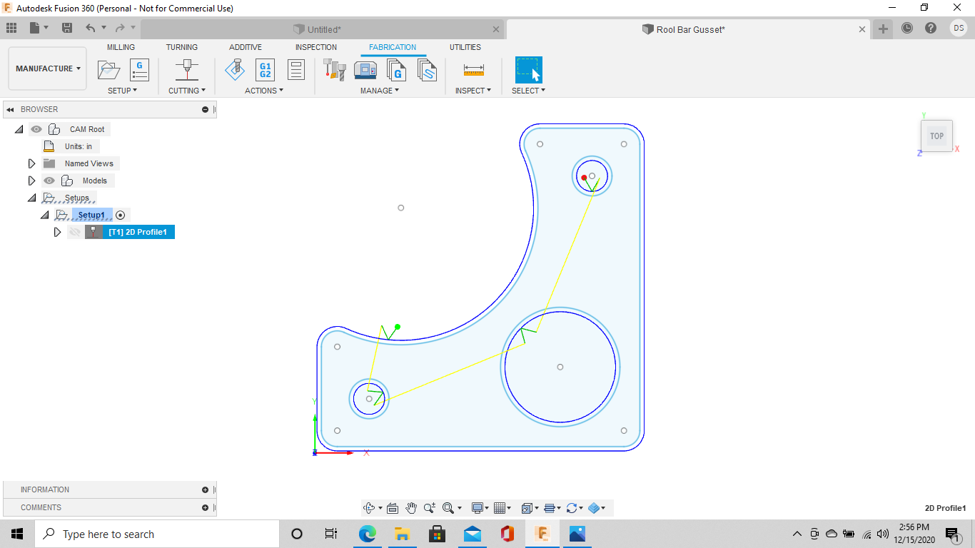
Yes Sir, and wont allow me to move forward… well I take that back… I can go to simulate but the lines come from the top of the page vertically downward and dont follow any of the contour shapes or inner circles
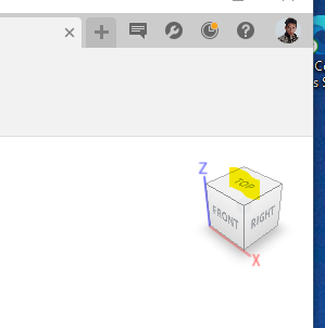
thank you… trying to reset everything now… I used the original setup… I missed that it was in z,
lets see how I can fix this
I really appreciate your help… this has been a mistake Ive been making all along…
going to have to work out this issue for awhile… I start out in x y… save the drawing in xy… then when I go to start manufacture it goes back to z … and I cannot seem to get back to xy
operator error
wifey will know…when she gets home
you have given me direction forward
thank you
Yep - that looks like you might have found the issue - or at least a good part of it. The axis orientation is important. When I do 2d stuff I usually try to do it from the “top” plane looking down on the part. It looks like you got the orientation from the side maybe? and it’s making the cut path on the side plane. Or something like that…@fortifyfabworks for the win!
When you import the dfx and choose the plane, choose the top plane and you should go smoother when you get to the cutting part. the XYZ orientation will be more straight forward - you may not need to mess with it at all or just choose the bottom left as a starting point in the setup config.
File->Open->Open from Computer will bring in a DFX on the top plane by default…interesting…never tried it that way.
I’ve always used the Insert -> Insert DFX and it pops up a dialog to choose the plane and dfx file and brings it in on the selected plane. I usually choose the top plane, so it does effectively the same thing…but anyway, that’s new to me…
A big thank you to all of those who helped me… because today was SUCCESS… first dxf file made all the way through… and while I didnt design the file I am now making progress… before I was thinking hey I might not be successful at all with cad.
So… here is what I found… all the videos and all your suggestions directed we would be working in the xy plane… and I always ended with z… unknown to me and after much searching I found that I had not set my “preferences” correctly… actually I didnt even know there was a preferences tab… which I found under the current version (different location in older versions) that ended up being under my name. In there I was able to set y always up … units of measure and a number of other units. After I clicked apply I had to exit the program and reopen it and viola… now its the way everyone said. xy plane… and units default to inch
Fortifyfabworks thanks for your careful eye… you caught my mistake
james… thank you for being gentle on a virgin…
Now… Im going to try some other files and see if I can replicate success…
The only sad thing about all of this is now you wont get to see me throwing my laptop into the air and shooting it with my shotgun… ;-(
