It looks like you are getting good help with your cube…
Toms method is valid… but the method I use for testing the kerf width involves a little less math.
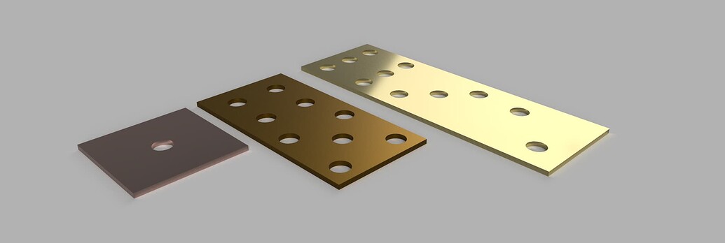
Draw a square with a round hole as suggested above… BUT choose the center offset to cut down the center of the line. The difference between what you drew, and your finished product is your kerf.
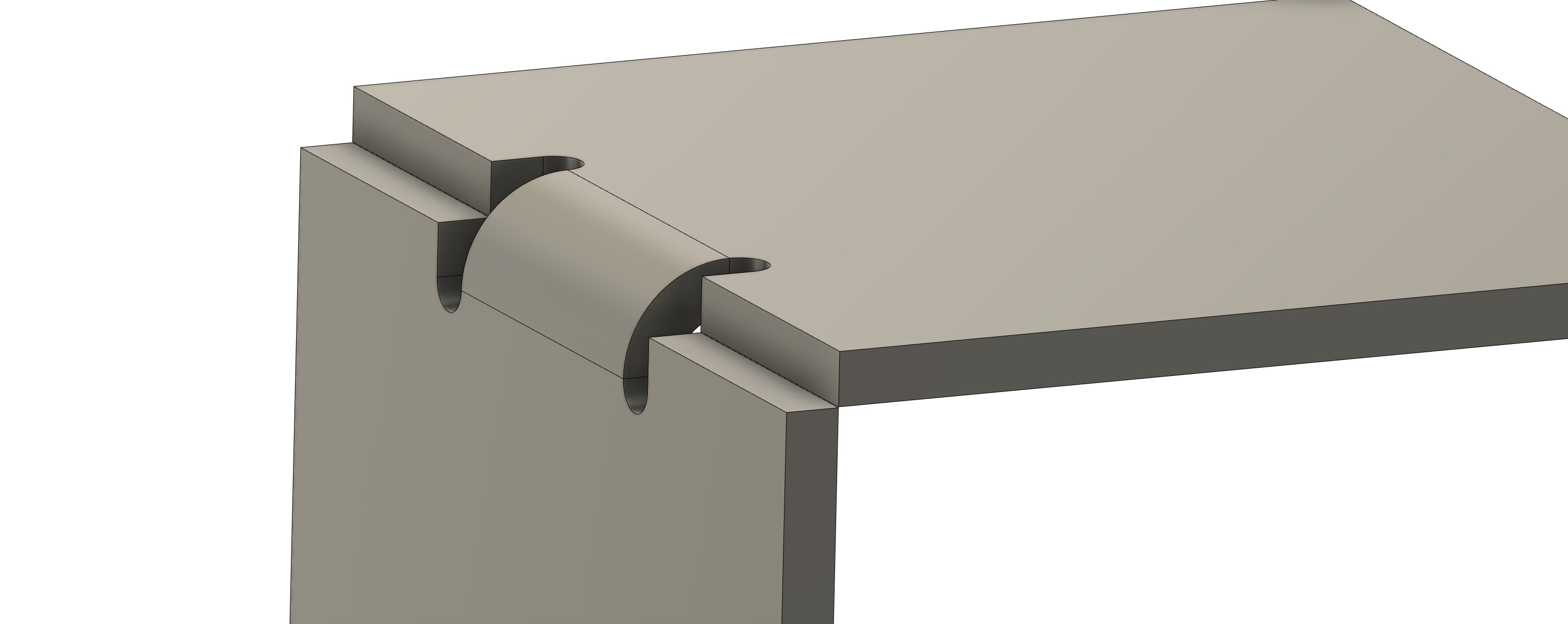
There are some “kerf” width issues happening from the lack of preforming a kerf width test and using that number in the program and using the wrong side of the line to cut on. imo One of the main issues with the op’s model is the lack of bend allowances which will produce gaps when hand forming like pictured above. When hand forming ( most forming) the bend starts on the outside of the shape where if the op wants the corner to fit tight the bend would have to be notched back some so the bend could start on the inside of the shape.
WOW so much help on this one. THANK YOU! I just want to say this community is amazing.
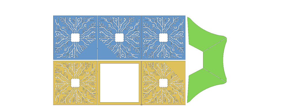
@TinWhisperer Thanks for providing the detail on the foldable cube. Yes this was really my first piece since getting into this CNC cutting. I didn’t apply any real method to figuring out the bend and kerf cut, but the idea was to have spacing in between as it will likely be a prototype for Teseract cube. Having the gaps will allow light to come through it. (LED glowing cube, ask Loki).
@72Pony - Is this offset setting in one of the post design options?
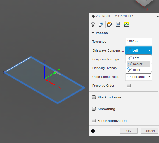
@ChelanJim - See screen shot, is this changing the cut path to the outside? When cutting relief cuts like this, are you saying with a kerf cut setting, if the relief cut is too narrow, the kerf cut eats into the design because it all doesn’t jive mathmatically?
You are correct with the red arrow on the outside, it will now be cutting on the outside.
You are also correct that if you kerf width is set too narrow, the torch moves too close to the line and will burn away more of the metal. As we all have been saying, "you want your kerf to be set correctly and then the torch will position itself, 1/2 the thickness of the kerf width.
What Erik is talking about is the sideways compensation. It is on the fourth tab of the toolpath:
Thanks a bunch! Let me digest all this info and set up a few tests with these settings and I’ll report back. Again, thanks for all the great info on the cubes!
I didn’t want to create another post as it’s a bit related to this. What setting starts the cut like this? The lead in? It’s cutting into the project. This is a V day last minute idea here!
Generally your cut is going to be a “left compensation” meaning that the torch is to the left of the ‘good’ edge. The reason you are having problems is because you are cutting out of the middle of the metal and there is no outside cut. The CAM operation is expecting some “outside cut” such as a frame around your piece.
But take a look at the link I provided. You need to be running the simulation and you would have seen the lead-in/lead-out on the wrong side.
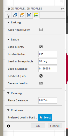
@Phillipw , the lead in where it starts the cut outside, the lead in and exit ? What is ideal on small lettering like this. It seems that I’d want the lead in and exit to be very small, like a pin hole. Are these the settings?
If I am understanding, the sweep angle is what is showing in the screen shot above, the lead in /out V shape? The distance is the length of these? If I make them 0, then it would be a pin hole?
Lastly, the Lead in position is used to customize where it actually leads in? So in small lettering you’d want it to lead in where it has the most space?
I always use lead in and outs. If you set them to z you will only have the pierce. With the picture you provided it looks like you are cutting on the wrong side of the line. You want to cut from the scrap side so you don’t see those. I would say if you measure that piece the size is off also. Here is a piece I did with lettering. Notice you can’t see the leads.
You can have issues where leads won’t fit. I try to do a a minimum of double my kerf on thin material and much longer on thick.
It has been forever since I have done f360. One of the forums finest can help you get your settings correct.
@Phillipw , thanks! Yes I figured out how to cut on the right /left side of the work from @ChelanJim . Then I realized the lead in distances are pretty long and for small lettering this could become a problem. I ran into an error last night where the simulator would skip over one of the letters, that was because where it was leading into the letter, there wasn’t enough room. My goal is to get a good configuration that can cut smaller details for intricate designs.
That Garage sign is AMAZING! I can’t wait to start some of these larger projects once I have this thing dialed in! Tons of settings!
Why don’t you share one of you test cut f3d files. One of us can show you what we mean and how to best get all of the contours picked.
Tin is telling you a great way, as a novice, to assure that your pattern is cut without the worries of inside or outside cuts: extrude a body. Then when you go into the CAM environment you simply pick the face. Fusion will figure out the contours and whether they are inside or outside cuts.
But you are right: Some of the contours are too small to accept a typical lead-in/lead-out scenario. That is when you will learn how to make a separate tool path to pick up those small features.
Showing us pictures of your attempts and moving to another without truly looking into the specifics of each “teachable moment” is, perhaps, missing some great stuff. All your questions are good but let us help you get the basics down.
If it were my issue, I would like to see how to cut the original box without errors. If you got that resolved, I think you would have seen how to approach the “2024.” Once you get the “2024” resolved, you would definitely see how cutting letters will make you change some of your assumptions.