I’ve bought an Edge Technologies Pro Traming tool that measures 5 inches on center. Today, I took the machine apart to do some maintenance since I was noticing visible grooves when I would face a part. The fly cutter is set to about 2 inches in diameter and I would measure the peak of the groove to be about 0.0015". So, I had resquared the machine, replaced the limit switches with the new waterproof ones LS is replacing them with, and then I began my traming process in the middle of the bed. I managed to get my tilt and nod to under 0.001, hovering around ±0.0005" over 5 inches which is acceptable. When it was time to face the plate, the left side faced beautifully, abosolutely no ridges at all. As it moved closer to the right side of the machine, the grooves came back once again peaking at about 0.0015" then zeroing it out once the dial indicator moved past the peak.
Is there something off with the gantry, as if it was warped moving towards the right of the machine, or is it something to do with the flycutter? I would like LS to help out on this one since I’ve unfortunetly have been having troubles with traming since the day I got the machine. I’ve watched all of their videos on traming and adjusting tilt and nod and sadly nothing has worked.
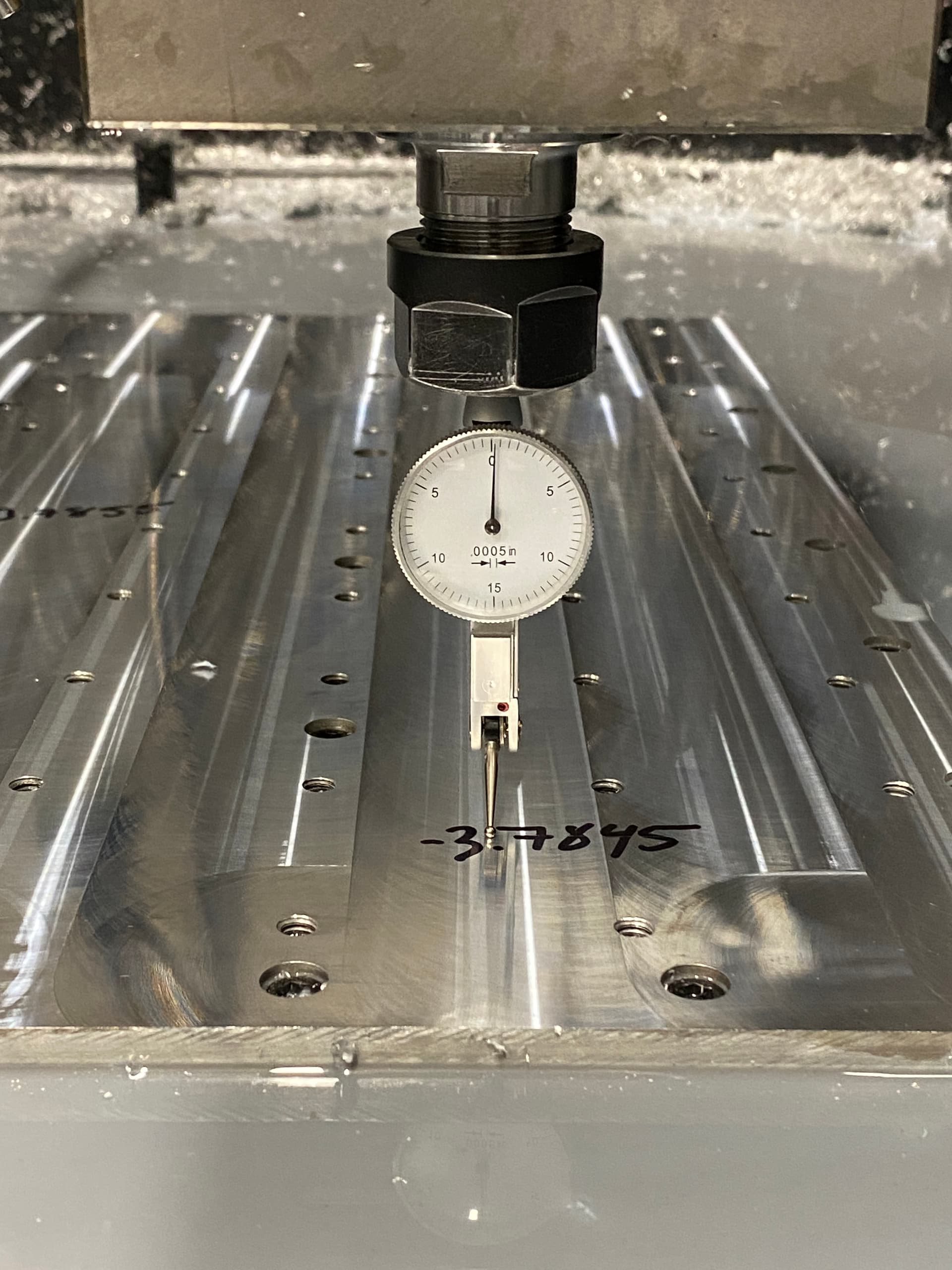
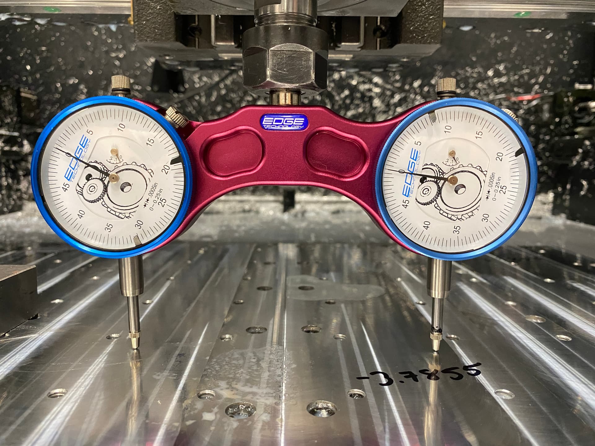
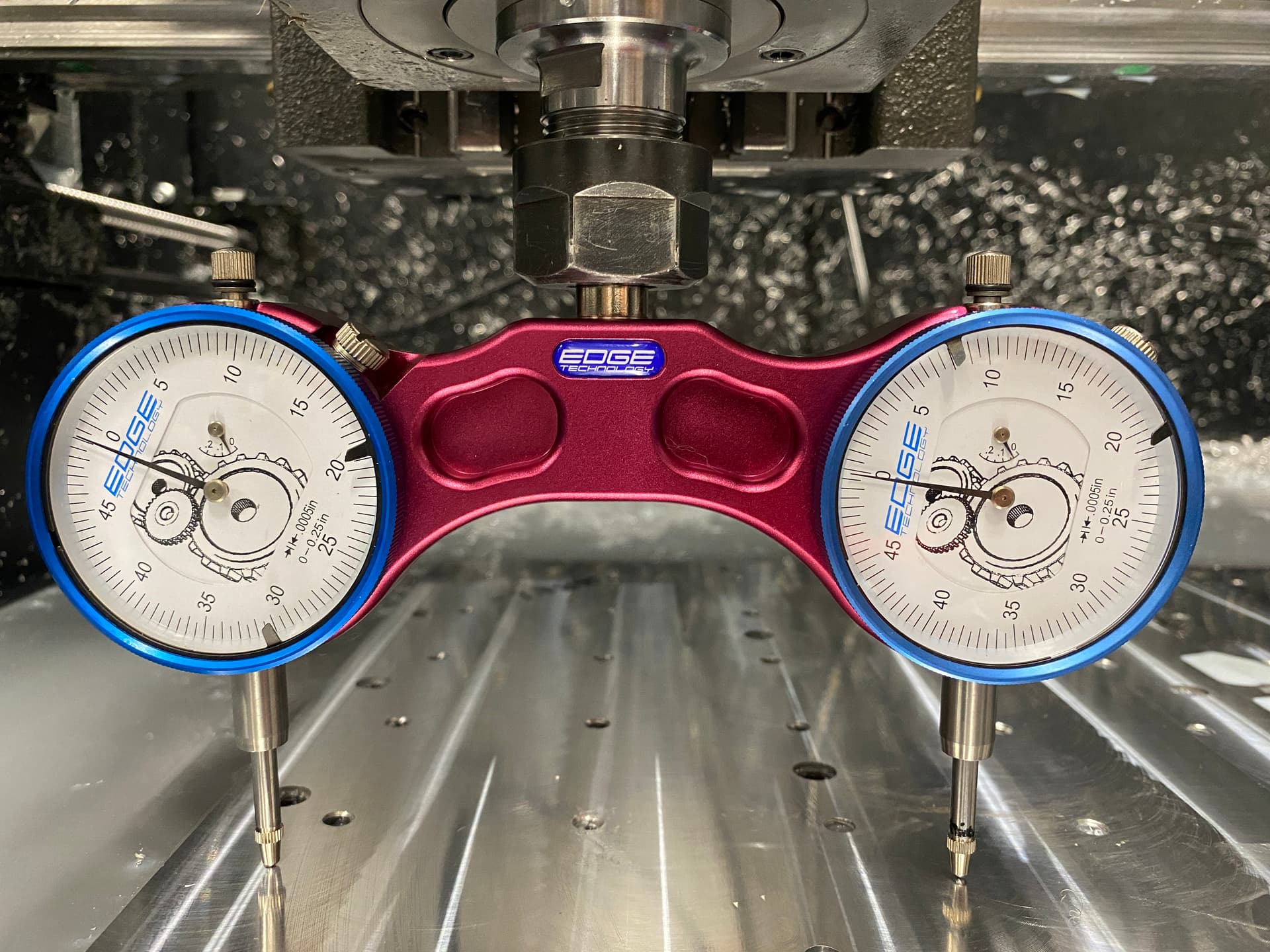
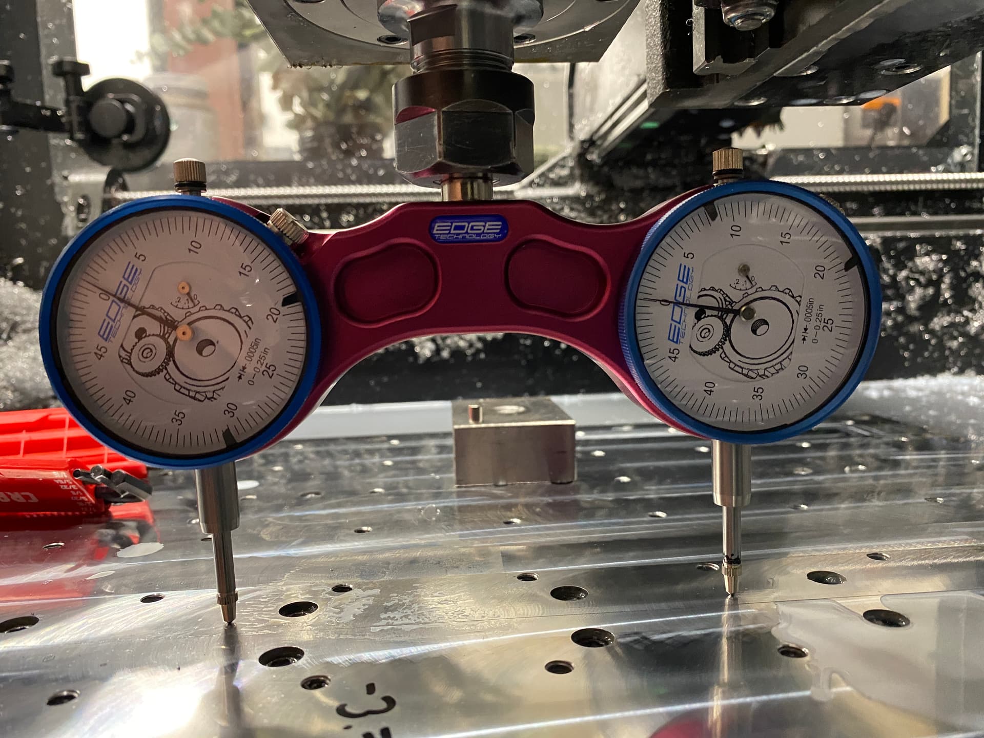
Below are some photos of the traming tool on the left, middle, and right side of the machine at halfway of the Y axis travel. There is also a photo of the tilt on the spindle which read out to be 0.0005". The photo with a bunch of numbers written on the bed is the height relative to the Z homing height that I measured using the touch probe LS provided, which is once again tuned to a runout of less then 0.0005".
Ive been doing some more work on the CNC trying to figure out where the issues were coming from so I decided to start from the very beginning, with the installation of the Y beams and rails. When I zeroed the indicator in the center of the rail, then moved it either left or right, I would get positive readings indicating that the rail is warped. I proceeded to take the beams off of the cnc and lay them flat on the ground and sure enough the were warped, as either end would be high and wobble. To double check it wasnt the floor, I rotated the beam 90 degrees to lay on its side and sure enough there was absolutely no play at all.
If I’m interpreting what you’re trying to show correctly. it looks like your Y rails aren’t parallel in Z. Banana shaped with the low spot in the middle. Loosen all the support plate bolts and see if they unspring.
The area that you are indicating (top surface of Y axis rails adjacent to the slot that the rails mount into) is not a machined surface. These Y axis rails are machined out of extruded cold rolled bar and are not flat nor square. When we machine these bars, we clamp them in special fixtures that limits the magnitude of distortion of the bar due to clamping. This to ensure that the linear rail mounting surfaces are flat and straight after unclamping. We inspect both the flatness and the straightness of these slots and reject anything greater than .003" over the entire span.
With respect to your tramming issues, that appears to be caused by the gantry itself. Basically the Z alignment (as viewed in the Y-Z plane) changes as the carriage traverses in the X direction. This directly affects tram accuracy among other things. We check alignment of the upper and lower linear rail references edges w.r.t to the gantry mounting surfaces and if one side varies by more than .003" than the other, we reject it. But that .003" can still create a tram issue especially evident when using the fly cutter. The only way to correct that is to shim between either the upper lower linear rail and its corresponding reference edge to ensure that the upper and lower reference edges are exactly parallel.
Thank you for your feedback. When you mention to " shim between either the upper lower linear rail and its corresponding reference edge to ensure that the upper and lower reference edges", are you saying to place shims underneath the linear rails and using a dial indicator on one rail to ensure they’re parallel?
Since we had the machine taken apart, I doubled checked coplanarity, and it was about 0.003". I fixed that and brought it in to about 0.0005". Then for tram, what I did (assuming the flat surface on the top side of the vise is flat) I shimmed the vise so that it was parallel to the motion of either the x or y travels. I fixed the tilt and nod of the spindle and over 5 inches, they read 0.0005".
Once I put everything together, I installed the fly cutter and went for another pass. Like before, the left side of the machine didn’t leave a single highpoint, but as it got to around the middle of the bed, it started leaving these highpoints as if tram was off (which it shouldn’t be) which got worse as it moved further right.
The tram of the spindle is good. Coplanarity is good. What would be causing these high spots? Runout? Possibly a defective X-axis gantry beam? Linear rails that may not be flat?