Friends, I give up on trying to figure this one out without bothering anyone. I need some help or suggestions. I tried running the program using different settings, but it just repeats the problem. Cuts a hole and stops. So, I weld it closed, level it, tweak it, and try again. These are the details:
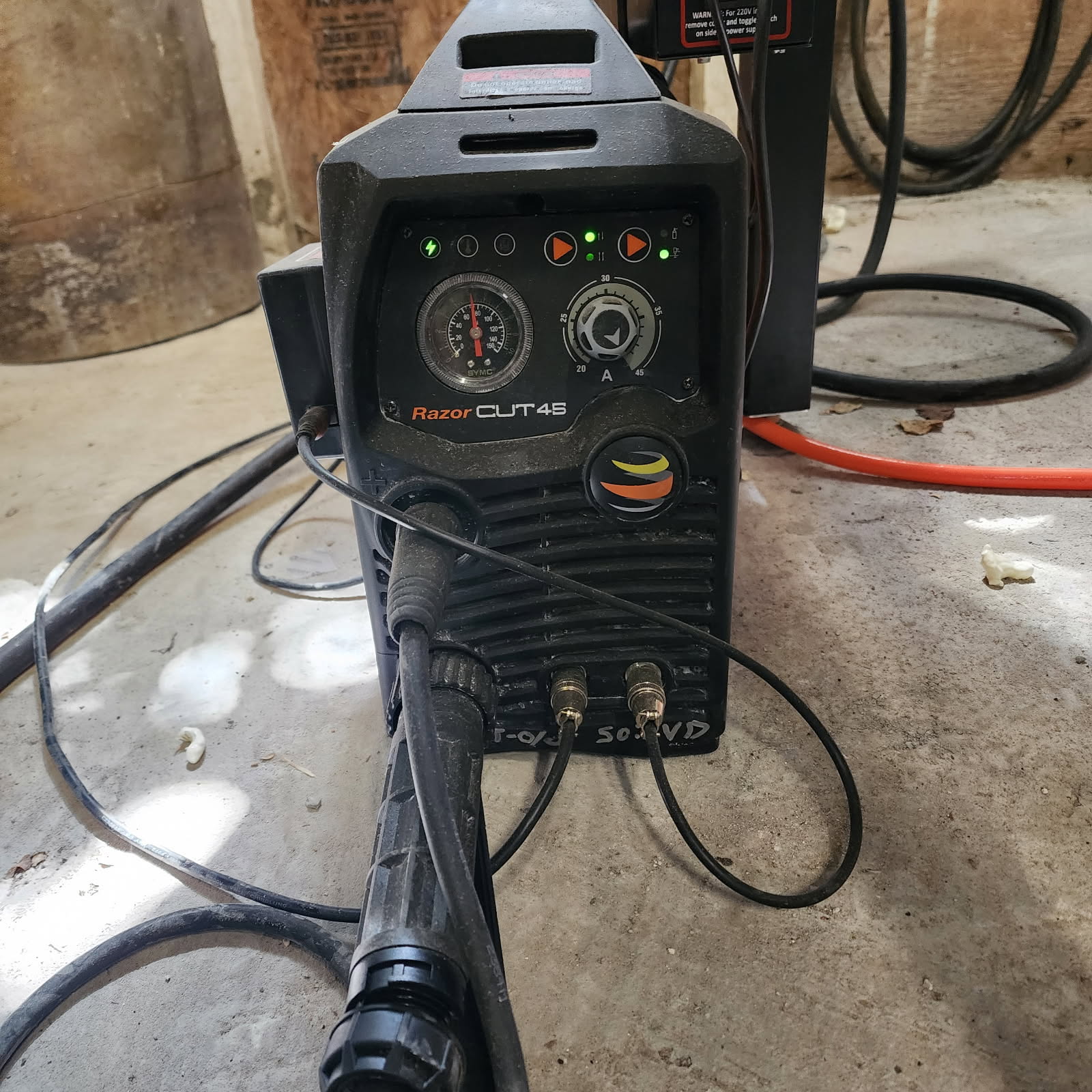
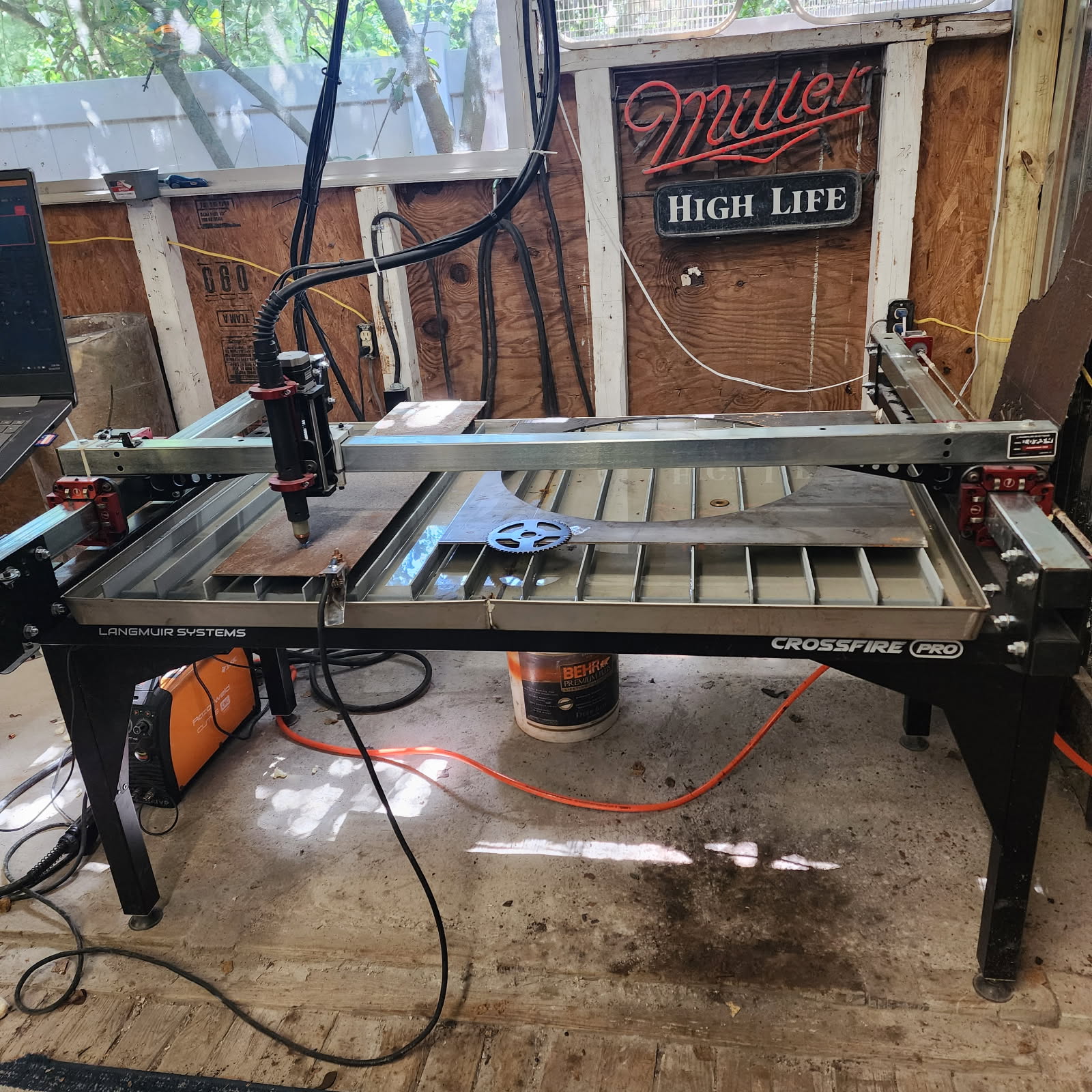
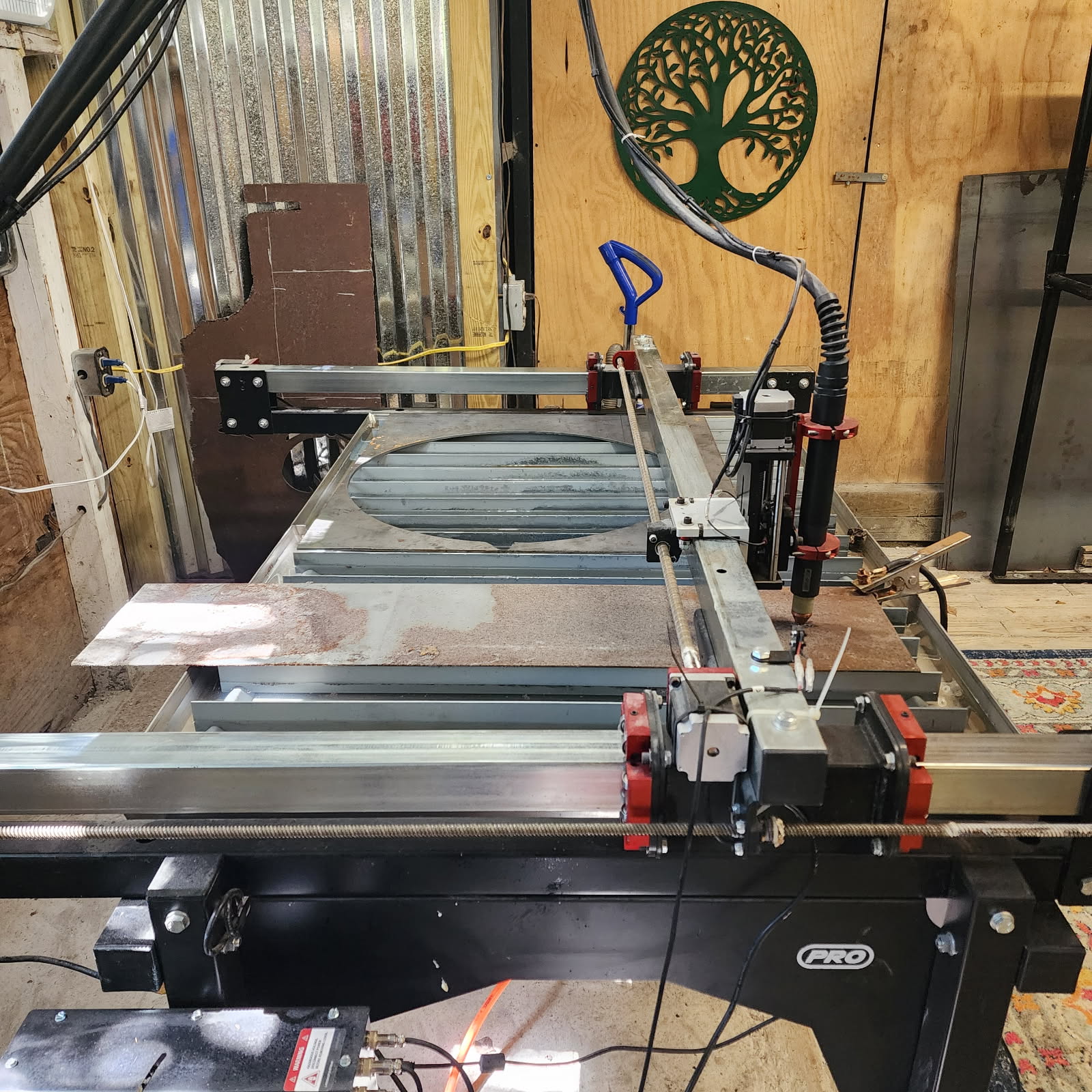
With 3/16 soft steel grounded directly. Pierce Delay 0.7. Also tried 0.8, 0.9 and 0.6. Pierce Height 0.15, Speed 85, Cut Height 0.06, Lean in radius 0.05, Lead in sweep 90, Lead in distance 0, (for cutting 3, 0.21 holes) Piercing clearance 0.04, Kerf width 0.05, also tried .04 and .06, Air 75 psi, Dry, Cutter set at T2. Main breaker 60, Leads between main and second box #4, Leads to compressor 6g w/30a sw, Cutter 6g w/30amp sw. I’m cutting a 5in sprocket with a 1in center hole, 3, 0.21in bolt holes, and 6, 1in outer holes. 54 teeth. I also tried this using the necessary data changes on 1/8 in steel sheet. The program begins with one of the 1in holes. I hope these details make sense and help. Thanks for any advice. Dave
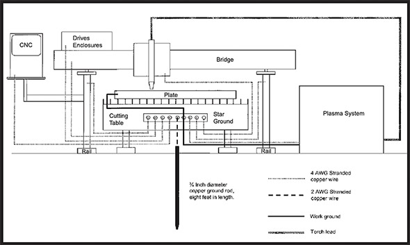
I was having random odd issues and implemented the following grounding which as solved my problems:
Yes. It works. Most people don’t require it. But it does solve the issue.
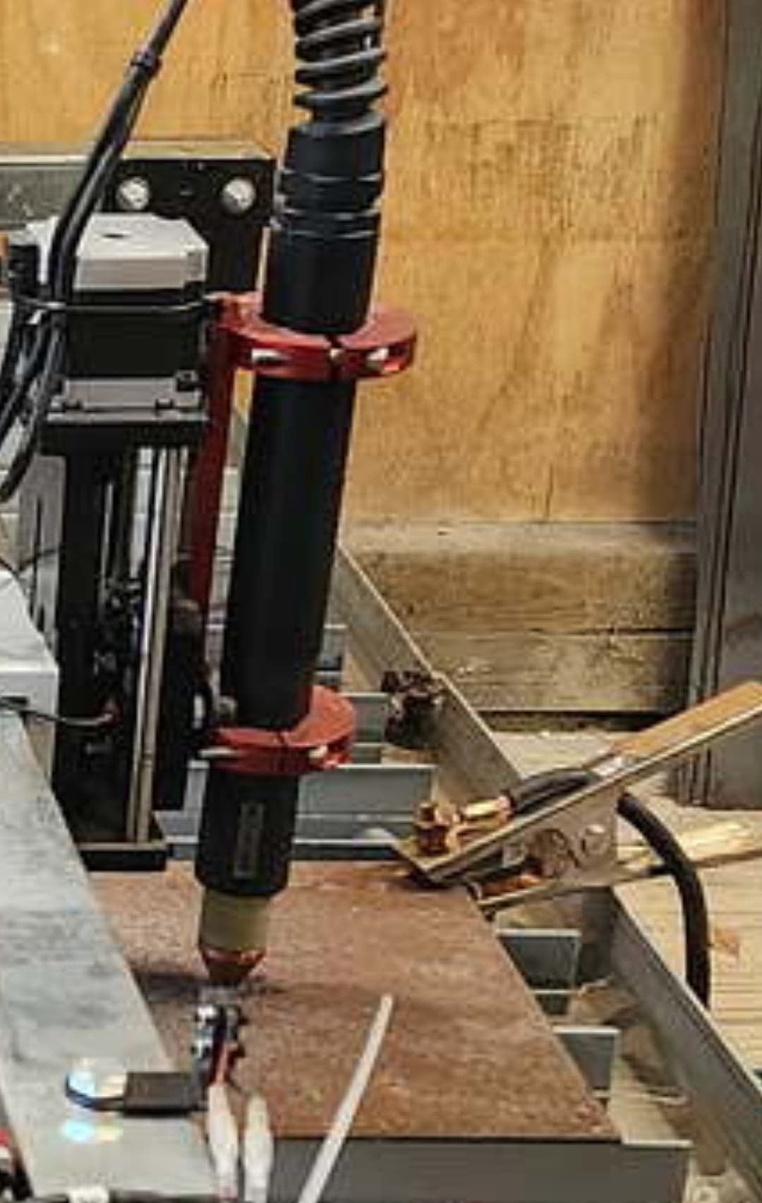
Maybe it’s clamped a little low on the torch.
Can you post your actual cut program maybe there’s a decimal point in the wrong place somewhere.
Have you tried it with your limit switches unplugged.?
Does it fail when the torch height control is disabled?
Can you make a straight line cut within fire control?
JDT, I should have a grounding rod laying around here somewhere. I’ll install that tomorrow. But I’m not sure what you mean by positive work piece. Is that the electrode circuit? The control box should be free. I used the insulators to mount it, but I’ll check it for continuity against the table. For the laptop, I mostly use it’s battery, so that should be good. I’ll test the printer cable shield against the table for continuity also. I understand the control system cannot be grounded, which I don’t believe it is, but I’ll check. Please let me know about the positive work piece, where to connect the ground to it. Thanks
TinWhisperer, I set the torch to the clamp by the instructions. It was wrong before the previous project but I had corrected it. The limit switches, I meant to disconnect those damned things a while back, and forgot. I’ll fix that tomorrow. How can I post the cut program? Just upload it? Thanks.
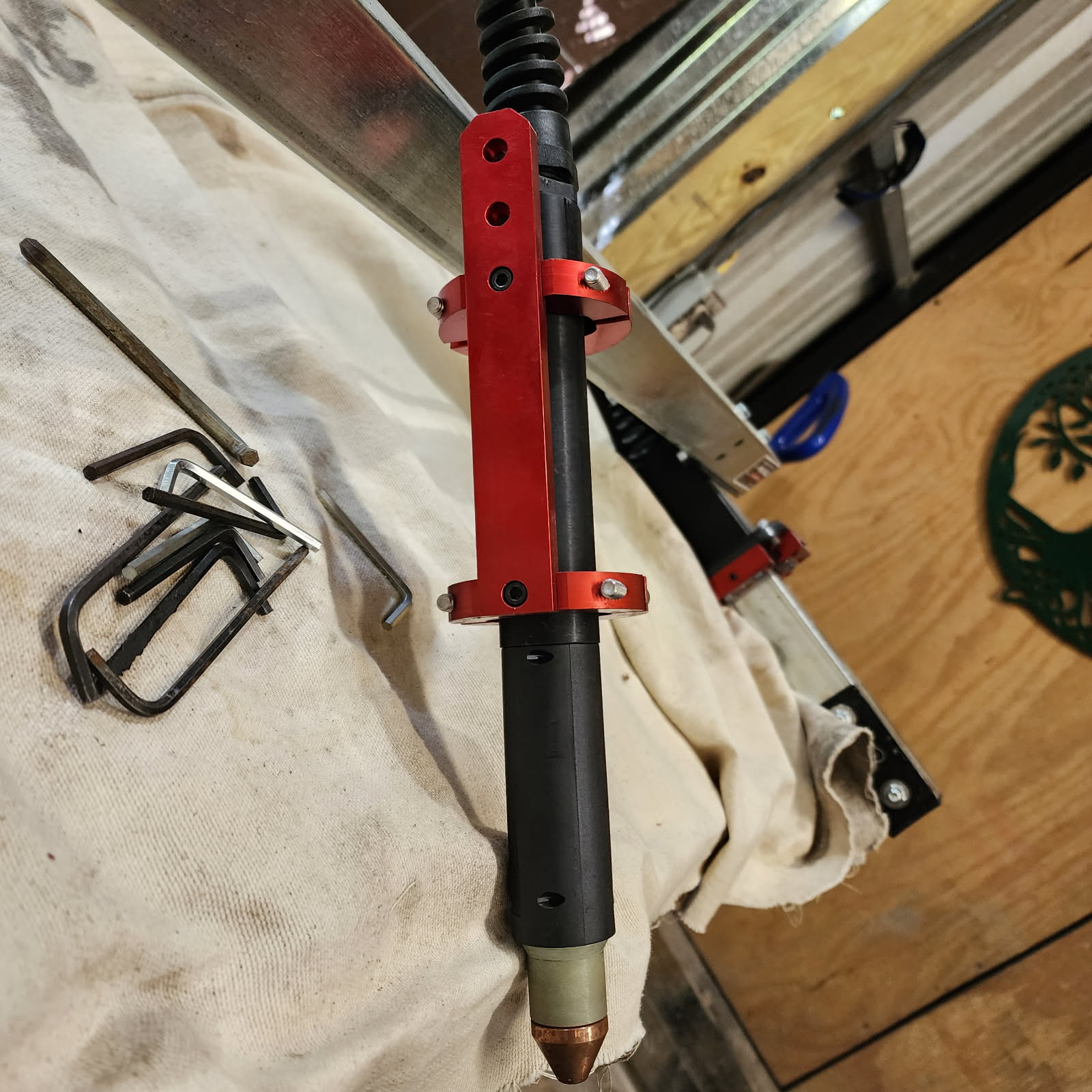
If you look at the red torch mount the one ring is mounted to the one hole at the far end and then there are three holes at the other end .move the bottom ring up a couple holes. I think you end up having to flip that amount upside down so the langmuir systems s logo is upside down with that ring moved for it to work correctly. The bottom clamping ring should be above the seam line on the torch body.
Yes posted to this topic. I NC files and TAP files are acceptable to post but if they’re not you’ll have to change the extension to something else temporarily. If you’re using fusion 360 you could also post your F3D file.
Now that is correct.
![]() On to the next step then.
On to the next step then.
If you get the torch moving before voltage detected error, TURN OFF THC and try again. Quick and easy test to eliminate or verify a problem.
Sounds good Sticks. I’ll do that. But first I’m going to ground out everything except for the operating system. I should have done that from the start. I don’t know how that first project got through but it did.
It didn’t work. I earth grounded all 4 motors at their mount bolts and the table. I even turned the fans off. Used computer’s battery. Compressor was off. There is no continuity between the table and control box or motors, unless I connect bus to the ground rod while the control box is plugged in. But of coarse there is no getting around that. I have several other headaches to deal with and then it’s back to the drawing board. Pretty frustrating.
R SPROCKET2.nc (14.4 KB)
Did you connect your work clamp cable directly to the bus bar? This is DC voltage and will not affect the cutter. The next step is a USB isolation device. Why do think its EMI? Have you tried another computer? Just bring me up to speed. Plasma, waterjet and laser cutting systems from Hypertherm
Relating to the cutter, I did the torch mount and the motor. Everything on wiring diagram except for the plasma box and the +clamp. Was going to ground those and forgot. Probably won’t make a difference, but at least it’ll be complete before I stumble into the next wall. I don’t have my other laptop loaded with this program, it’s slow a molasses.
Sorry, I take that back. I know I don’t ground the clamp. I’m feeling brain dead zombied out at the moment.
You do connect the work clamp to your ground busbar. Everything except the Langmuir control box. Sometimes the computer will try to save power by controlling the USB output. This will cause problems with the control board inside the control box. Let’s try one thing at a time. Also, connect a 10-gauge wire from the plasma cutter outer housing to the bus bar. This will create a Faraday shield from the internal energy.
The rod you drove into the ground is just a way for EMI to find an easy path away from the machine. It is only a ground rod by definition, but not in this case.
We need to try a 2-prong adapter on the control box. You know the type from 50 years ago, when the receptacle had no ground connection.
The CNC is grounded separately at the receptacle. Should I remove the cutter ground from the house ground circuit and wire it directly to the ground rod? I don’t think that will make a difference since it’s a common connection. Just asking. Probably over thinking it.