@ChelanJim , thanks. I’ll post the files and results in the next few days. I haven’t had a ton of time this week to implement a lot of these settings we discussed here. I’ve also been figuring out the workflow as far as setting up the computer in the shop, designing in the office, sending the files to the network drives etc… But I’ll show the results from all of your guidance. Also I’ve been designing some of these changes in Fusion to prepare for cutting. I’m learning its a bit of a process when you need to make a change, back to the drawing board! Some of the youtube videos I’ve been watching, they said “you can’t go back to these settings once you press ok”, referring to the Cutting tab settings. I realized under the “Setups” there is a history trail of each setting applied. Little did I know I kept reapplying the settings over and over. Not sure that messes up the drawing. I do 3D printing as well, so a lot of this makes sense from a CNC , XYZ perspective. I also need to pick up some more sheets of steel later so I have a good stock on hand, for all my mess ups, it can be expensive!
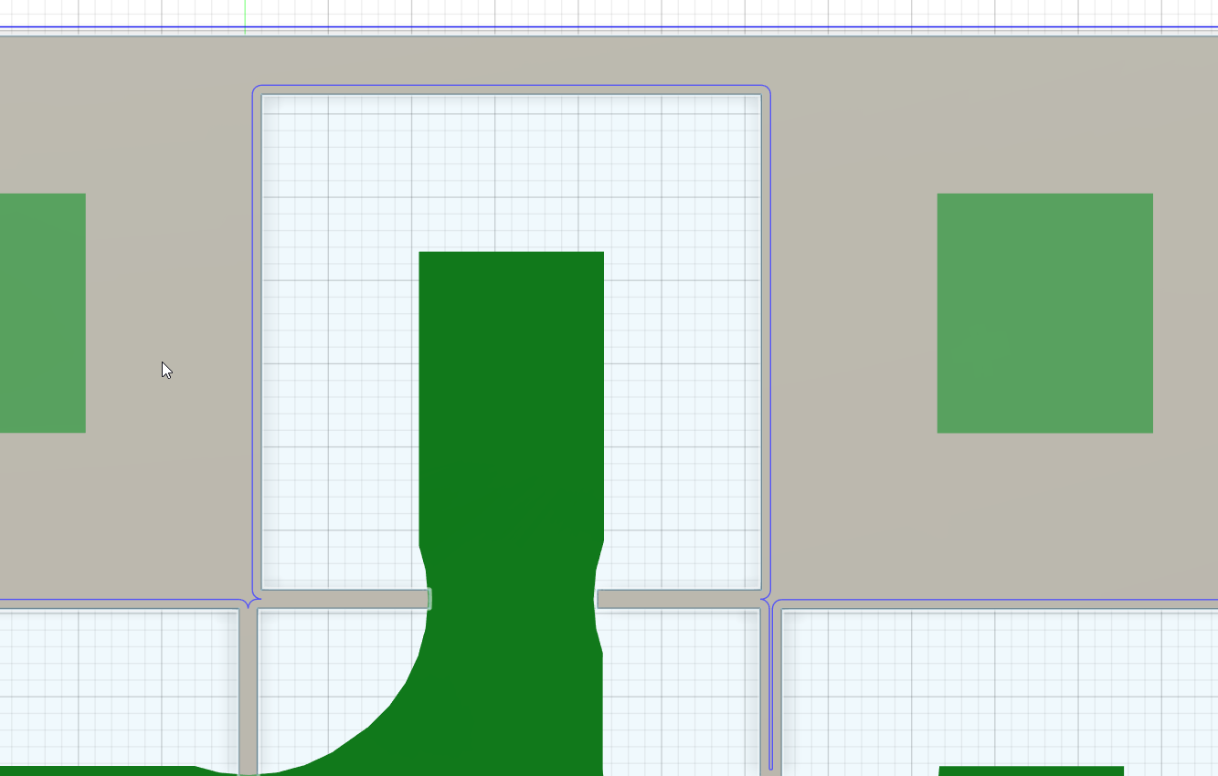
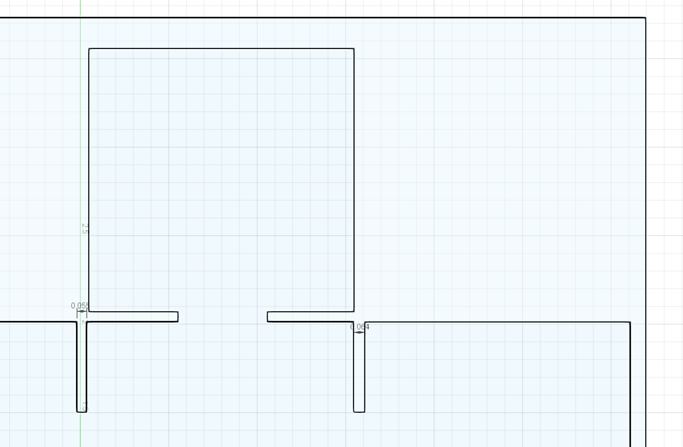
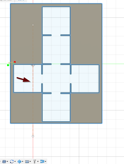
@ChelanJim@Phillipw@TomWS@TinWhisperer@72Pony Working on the foldable box. I have my kerf set at 0.055 in the Cutter Tab, I then fixed the cut direction to the outside. However, the tool path is not cutting the relief cuts when the dimension width is 0.055, but it is at 0.064
I mean what is the best way to handle this, one pass to eat out the relief line? Seems the kerf is coming in around 0.60 according to the dimension.
Just remove your pierce clearance and it works. Nope…it didn’t. Still looking at it…
The gaps that are not cutting are 0.055 inches or less. That have to be at least 0.056 for the torch to enter.
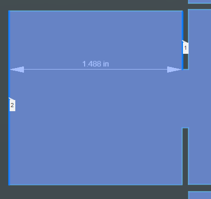
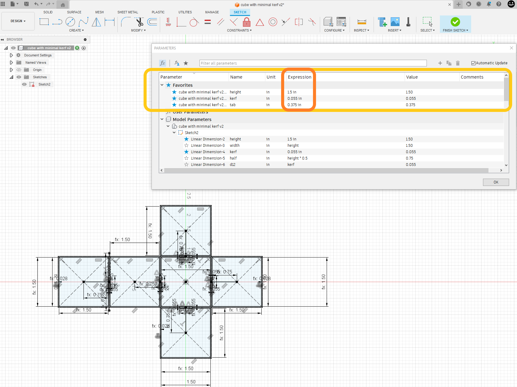
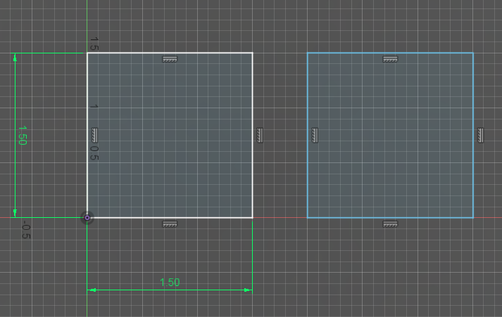
Here is another thing with your cube: It is not 1.5 inches on all sides.
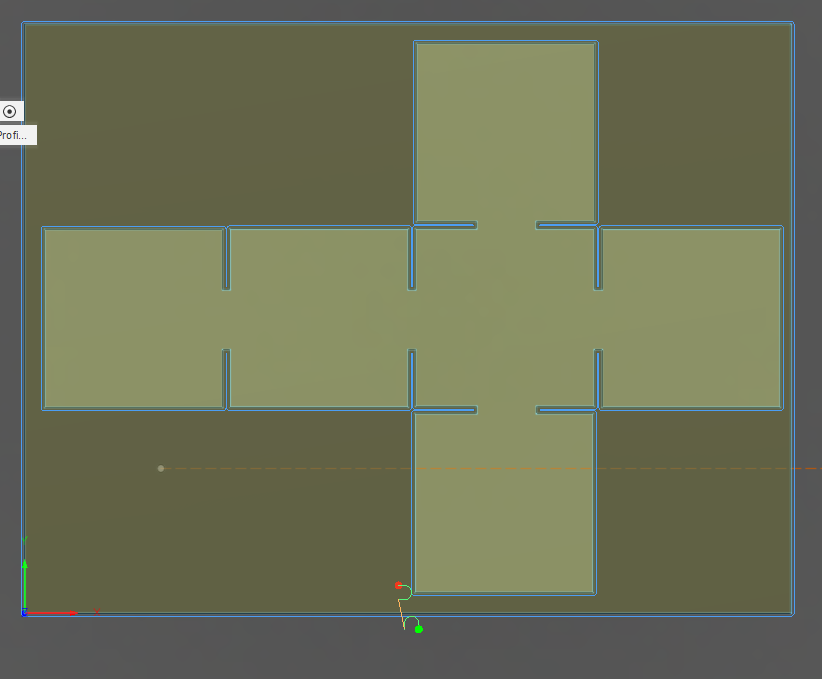
I made all of you slots a minimum of 0.06 inches, and the sides all 1.5 inches and went back to Manufacturing and allowed your tool path to run. Now it works. Box v5ChelanJim.f3d (212.8 KB)
@ChelanJim awesome! Thanks Jim. I realized I didn’t use any constraint dimension when I made it the first time and then figured out where the sketch dimension tool was! I was having trouble getting everything to move correctly. You almost have to start from the beginning with a constraint dimension so all other dimensions are based off of that point. I know this now!
Thanks for fixing. I’ll cut it out in the morning and report back.
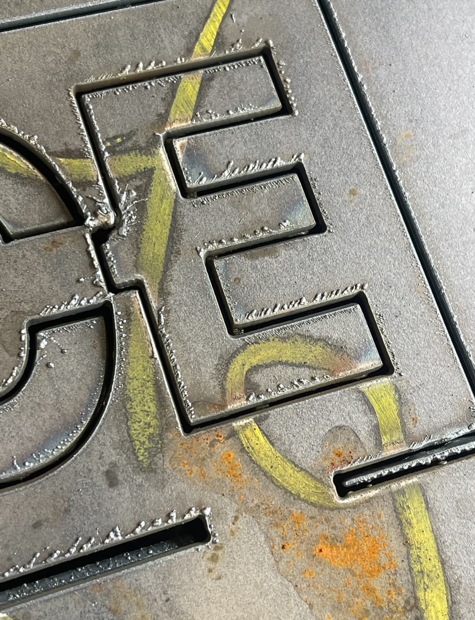
One quick question, I noticed my cuts are a bit slaggy on the back, I read that too much water in the pan will splash up and cool the slag causing it to stick. It’s not really chipping off like I’d expect, even grinding it takes a bit. Any suggestions on getting a cleaner, crisp cut?
Also should the cuts be 90 degrees? Mine seem to be beveled to the inside starting about halfway through the depth of the cut.
30Amp
60 PSI running
220v power
.6 mm tip
I’ve been using 100 ipm, as it seemed 125 was a bit fast for 14g plate. What speed should I be cutting at with 14g and the settings? I was thinking it’s too high amps for slow speed and it’s cooking it
That’s not the water… generally it is slow speed that causes the slag. It can be bad air causing consumables to wear out too fast. What plasma cutter are you running? Post some pictures of your slag.
Some additional notes about what I have personally experienced with backside dross:
I had lots of very hard backside dross when my torch was too high
Expect more backside dross for cuts that are slowed like in holes and tight curves/turns
As the nozzle wears out, you will have more of a spread of the plasma stream causing both a sliight bevel increase and backside dross.
Not at all. I got myself embarrassed by answering the question too quick with:
Then I HAD to figure it out!!!
I liked your version of cutting the slots. Obviously, that would be preferred because it is likely the double pass of the torch will likely widen the slot slightly. A bit fancier with your toolpath too!
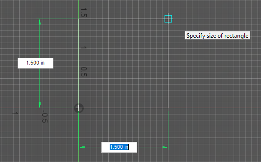
Yes, but if you know the square is going to be 1.5 x 1.5, you need to tab into the dimension boxes and enter the numbers. That will make them ‘constrained.’ If you make the box and are looking at the numbers as they roll with the movement of your cursor, when you click you have the 1.5 x 1.5 dimension but they are NOT constrained.
Does that make sense? Definitely a time when a video would clear that up better than just words. I don’t do videos.
In this instance, if I click with the mouse, I get a perfectly dimensioned 1.5 x 1.5 inch box due to the dimensions “snapping” to the grid marks but they will not be constrained.
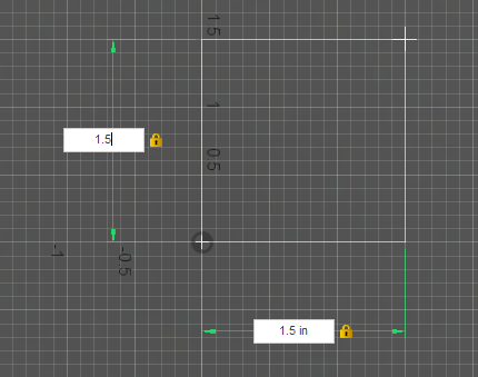
In this second option, I entered the 1.5 for the x-dimension and tabbed to the y-dimension and entered 1.5. Fusion puts a padlock on those dimensions: Constrained. They will never change unless I click on the dimension and change it.
So yes, if you expect/need/demand that a number be a certain number, you need to type in that dimension. I think you get that…I was just making sure. You can constrain a dimension at any time just by dimensioning: beginning, middle or end of your design. Sometimes your ideas change as you what dimensions are the most critical.
You will know it is constrained with dimensions because the lines turn white. If not constrained, they will be blue.
Edit: I am still learning “constrained” and none of my drawings are ever “fully constrained.” You can see in Tin’s demonstration that his drawing is fully constrained because it turned black. That is a lesson I have still not mastered.
Just want to again thank you all for all this help. Really its great to see an amazing forum and I know this is taking your personal time to contribute. Hopefully I can show my contribution over time as well. I didn’t reply to every reply in this thread but I am going through all these in detail so I can learn from the experts here.
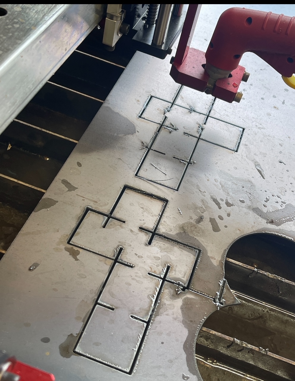
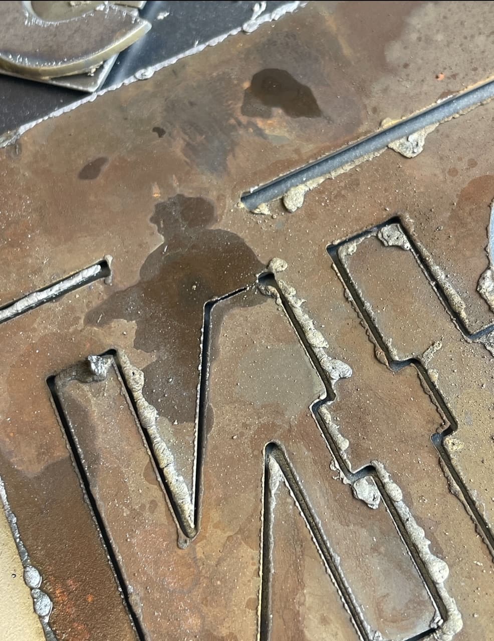
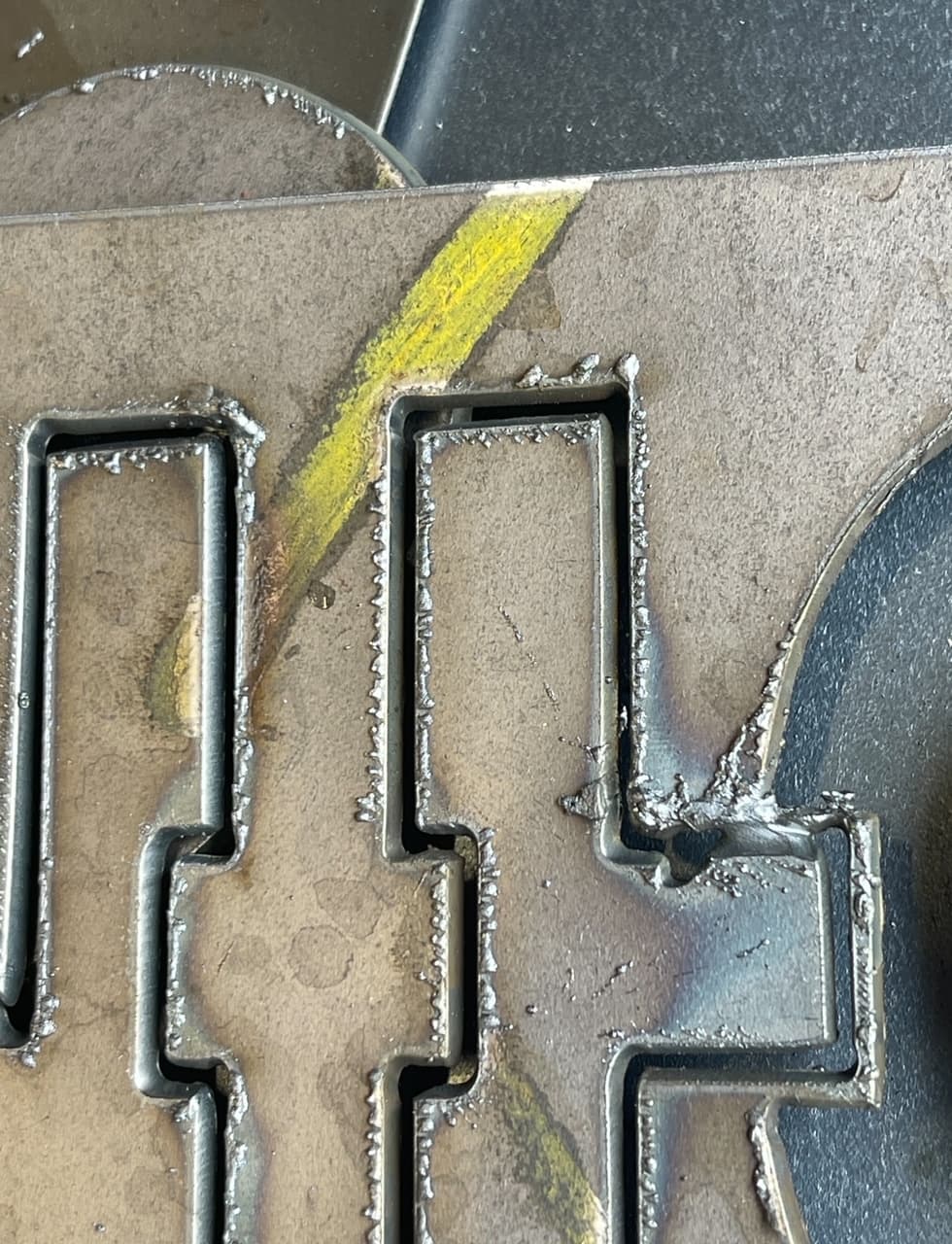
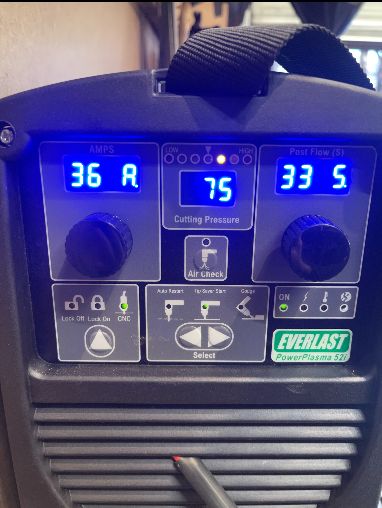
Here are the results of the cuts. Showing slag, the two boxes didn’t cut well. @TinWhisperer , it appears the box didn’t cut the last fold and was short. It also cut through the tabs. @ChelanJim box for some reason started cutting offset in the middle of the cut, then the torch cut off. Not sure if these were due to any of the post process settings after I received them.
I was cutting at 125 ipm, Everlast 52i at 36 amps. After looking at the bevels, they aren’t as noticeable from 75ipm to the 125 ipm, but still is beveled. You can see those in the pics.
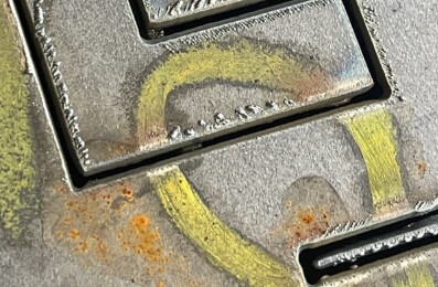
The slag on top easily just chipped off, the slag on the bottom is what sticks pretty good. Cut Height 0.059 in, Pierce height 0.15
Yes, I would bet you “dollars for donuts” that your actual cut height is too high.
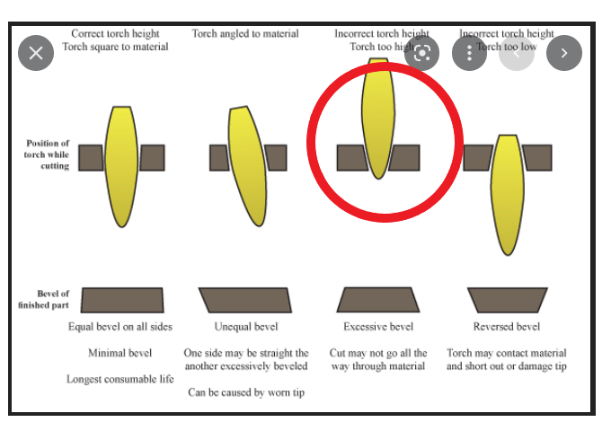
This photo shows you are having a bevel consistent with the torch too high off the metal.
You description of the heavy dross on the bottom would also coincide with that assumption.
You will need to stop the torch while it is cutting by pressing the space bar to interrupt FireControl. That will stop the torch movement and firing without changing any position. Then you can measure the distance from the torch to the metal. Send a photo and use feeler gauge or at a minimum a piece of 16 gauge metal to compare.
@PC-PlasmaCut cut height test.tap (224 Bytes)
Here is a .tap file you can run it and measure the height. This program won’t fire the torch and is set at .060.
Also share a picture of your consumables bet they are shot too.
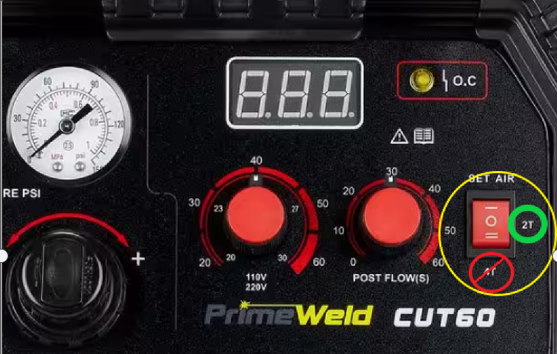
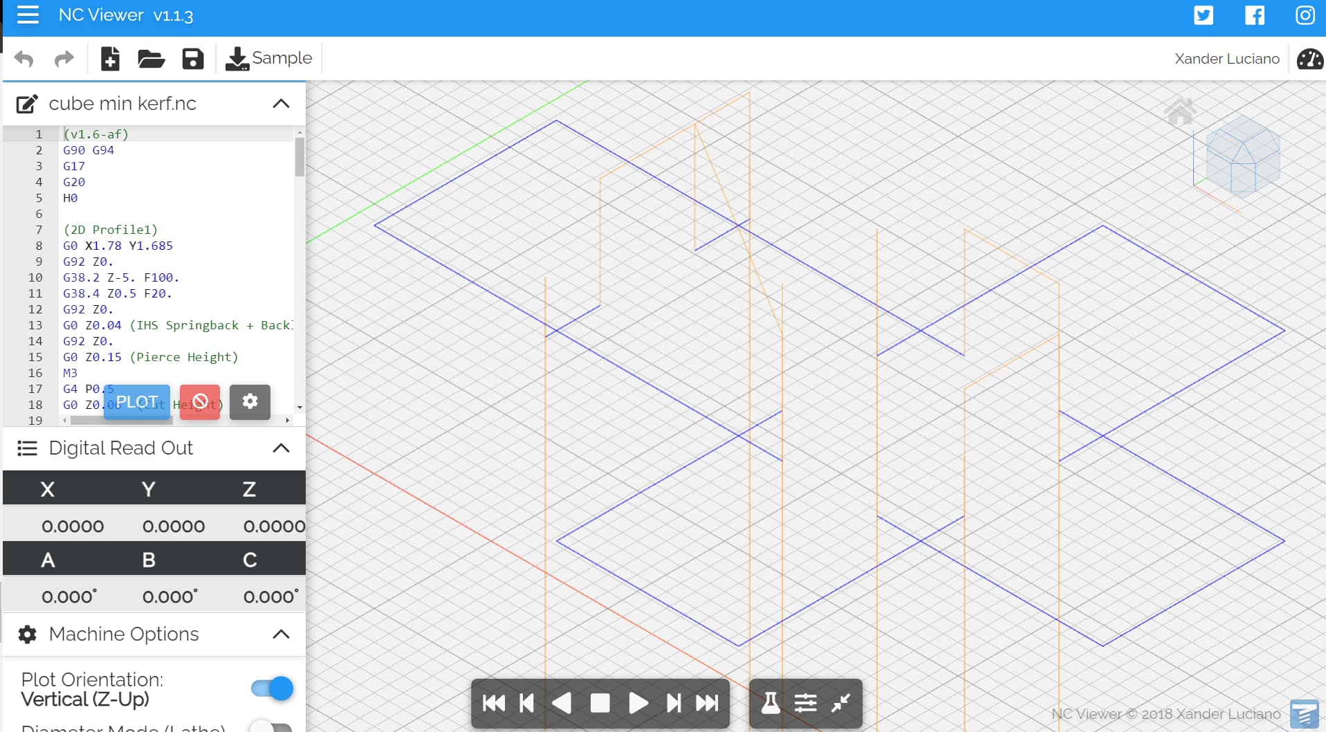
If you don’t see the tool path generating a cut on the construction line, that is not what is happening. Did you check to see if you cutter is set to 2T vs 4T?
I may have copied paste from another file on accident cuz I saw it on another file. Strange! I removed the line and recompiled the cut. I changed the cutting height to .058 from .060. Seems much better! Looks perfect.
I dont see that setting on my machine. It’s on Tip Saver setting