If I am using .6 and .8 mm tips, do these settings need to reflect that ? Commonly 1mm tip is what I’m seeing a lot of.
I’m cutting small designs
If I am using .6 and .8 mm tips, do these settings need to reflect that ? Commonly 1mm tip is what I’m seeing a lot of.
I’m cutting small designs
It is reflecting by telling the post processor what your kerf width is expected to be. When you do a straight cut, you could measure with calipers or feeler gauge.
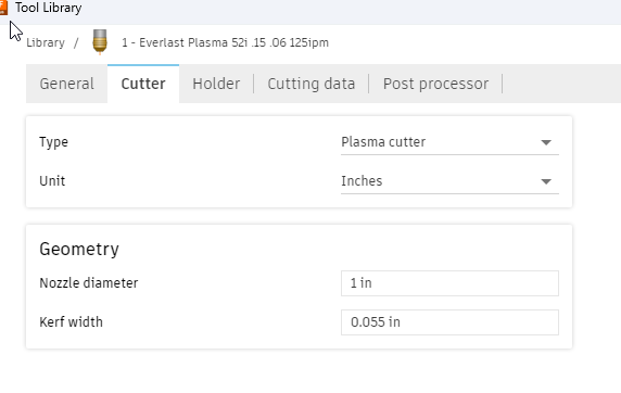
Nozzle diameter is not important. If you leave it at 1 inch, during simulation you see this 1 inch path moving thru the cut but it doesn’t affect the outcome of the actual cut. Nozzle diameter is a leftover from milling where the tool diameter needed to be accounted for so it didn’t accidently collide with your part. No worries of the plasma torch colliding with the party with plasma table with a flat sheet of metal.
So the kerf width is what ultimately gets tells the program how thick the line is so when you are designing the program can consider the width it? Then the nozzle diameter is just the picture of the simulator?
More precisely, the CAM processor takes the kerf into consideration when setting up the cut for your DESIGN line. The CAM Processor will offset the cut command by 1/2 the kerf setting on all cuts.
ok just to confirm. I need to make some test cuts, measure the cut width and enter that value into the Cutter tab ?
Because the actual cut kerf is defined by the tip, correct? I am cutting with a .6 mm tip. Seems the kerf cut is maybe close to 1mm, or slightly less
Measuring Actual kerf is simple.
What Tom says is precisely what the computer/CAM operation is considering. You don’t have to do all of the ciphering if you have your tool set up correctly. Let’s stick with the kerf width of 0.06 inches.
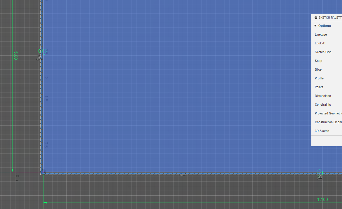
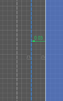
If you are cutting out a rectangular piece of metal that is to be exactly 5 inches x 12 inches:
The torch is going to be exactly 1/2 the width of your tool’s kerf width so that it’s finished edge is on the outside of the metal. The blue line indicates the center of the torch path: 0.03 inches from the edge of the metal.
Measuring Actual kerf is simple.
If I am understanding, then I have already cut /designed a square. Designed at 1.5" per the drawing, the final cut was 1.375 (1 3/8")
Current kerf setting 0.005
So…
0.005+ (1.5-1.375) = 0.13 ?
Does this mean my current kerf is 0.13, and that should be my kerf setting in the cutting Tab under the tool library ?
I mean, the cut of the plasma stream is then 1/8" basically. That seems big. Air presser 60, 0.6 mm tip, 30 amps on the everlast 52i, 14G steel, 75 ipm
I could speed up the cut now that I am cooking with 240 volt! Had to slow it down for the lower amps. I suppose a faster cut would make the stream a bit thinner?
Edit 0.055+ (1.5-1.375) = 0.18 ?
You have your decimal place, one off.
Usually, you just measure the gap in the metal with a cut that does not sever the piece of metal totally clear. That is your starting point.
…Wait, wait, wait…
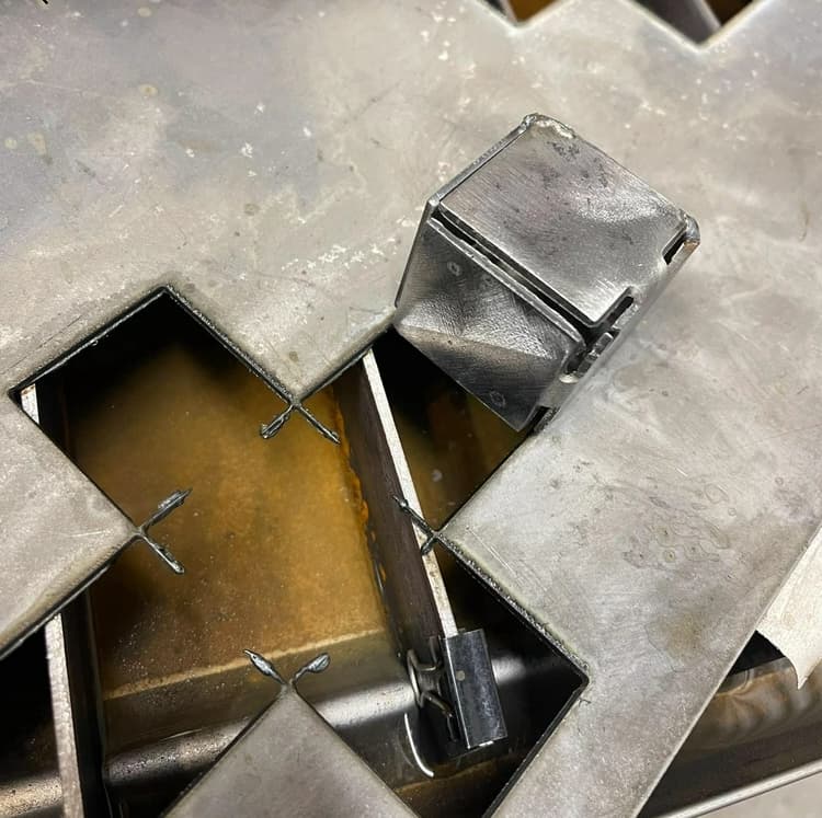
You are off by a full kerf width no matter how you go at this. Those cuts cannot have any bevel to be accurate for this exercise. Can you snap a picture and post so we can see what the edge looks like?
Did you use a ruler or a yardstick to make these measurements? ![]()
Continuing the discussion from Tool Libaray - Cutter Tab:
@ChelanJim , Yep I was off, current cutter kerf in the library is 0.055, so the formula above - .18. Still doesn’t make sense.
Whats wrong with the measurement, yard stick? Sorry this is all new to me. @TomWS
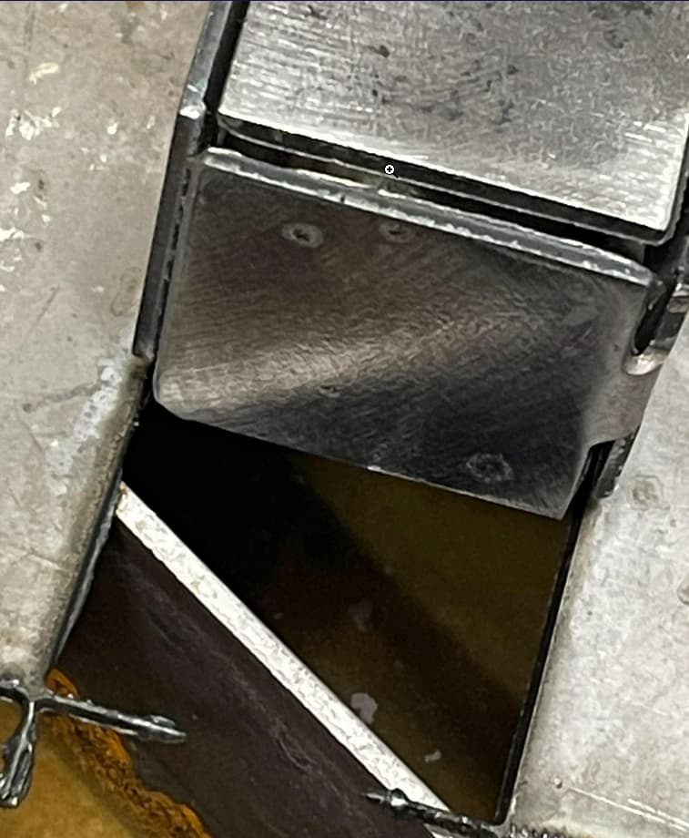
I am confused with your photo. You bent the metal that you are measuring?
It is easier for us if you insert the photo on this forum topic. That link is sending me to another app that I don’t have and crowding the photo out with ads.
Show on the photo, what was suppose to be 1.5 inches and how you got 1-3/8 inches. You really need to be measuring with calipers as you will not likely be able to measure with the accuracy that is necessary. Well, I can’t anyway. ![]()
There are areas on the edge of that metal that looks to vary. It is not a straight line. You can’t measure if your cut is not a clean cut.
I think you have jumped past a step: get a clean cut. Then you can nail down the kerf setting. You will be chasing your tail if you don’t.
For now, I would leave the tool “kerf” setting at .055. And revisit that later.
I’ll have to get calipers. I can tell you the the difference of the design in fusion vs the actual cut is about 3/32- 1/8” in.
I suppose the kerf setting now is too big as it’s eating into the design. Throwing the dimensions off
Thanks for the help. I’ll keep workin at it.
Are you doing a offset on your cut or cutting on the line?
You may be cutting on the wrong side of the line.
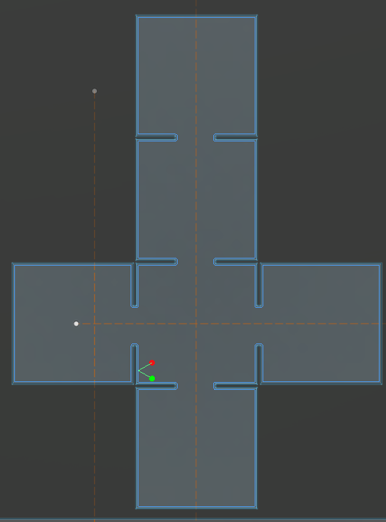
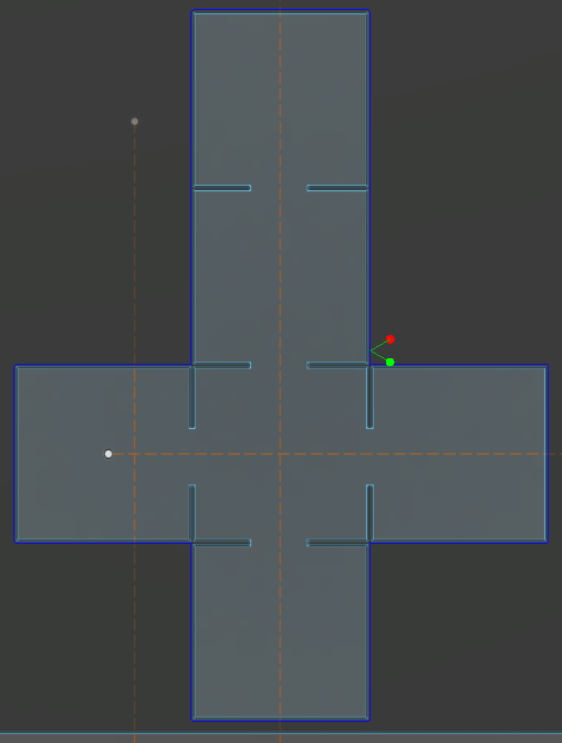
As @Phillipw points out, the only plausible way to get 1/8" of ‘kerf error’ is that you’ve used an inside cut instead an outside cut as was suggested. I think at this point, you should post your .f3d file so that someone who is NOT ‘new to this’ can help you.
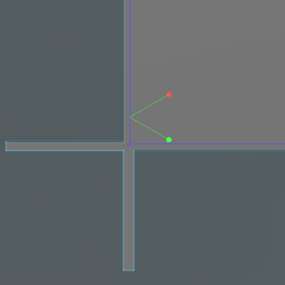
And once again, Phillip swoops in with the WIN!!! Not really a win. Phillip is right, you are cutting on the inside of your line:
Close-up:
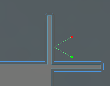
Which means, of course, that he won’t be able to cut the slots since they are too narrow for a 2x kerf.
@ChelanJim you know the saying even a blind hog will find a acorn every now and then.![]()