When my parts get here I have a buddy that is a very good electrician it’s what he does for a living and hopefully he can get it figured out for me. I will then share it with you once I have it working. I was wondering if you could save us some time and let me know what orientation you put your dip switches. Thank you for your time.
The Thermal Dynamics Cutmaster A60I manual does cover this topic.
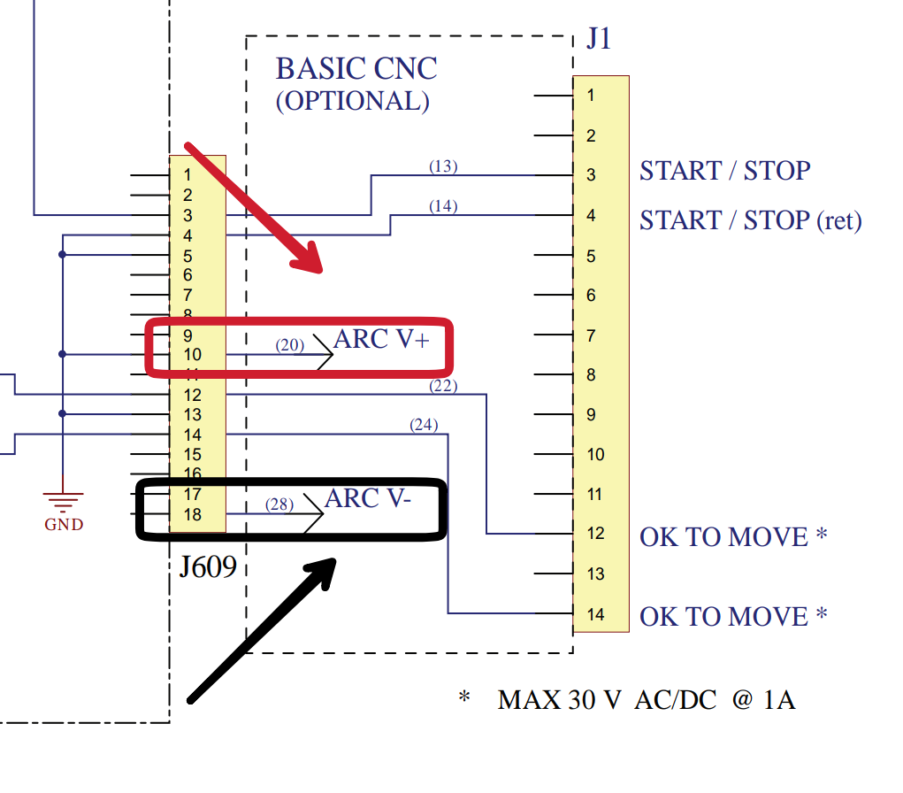
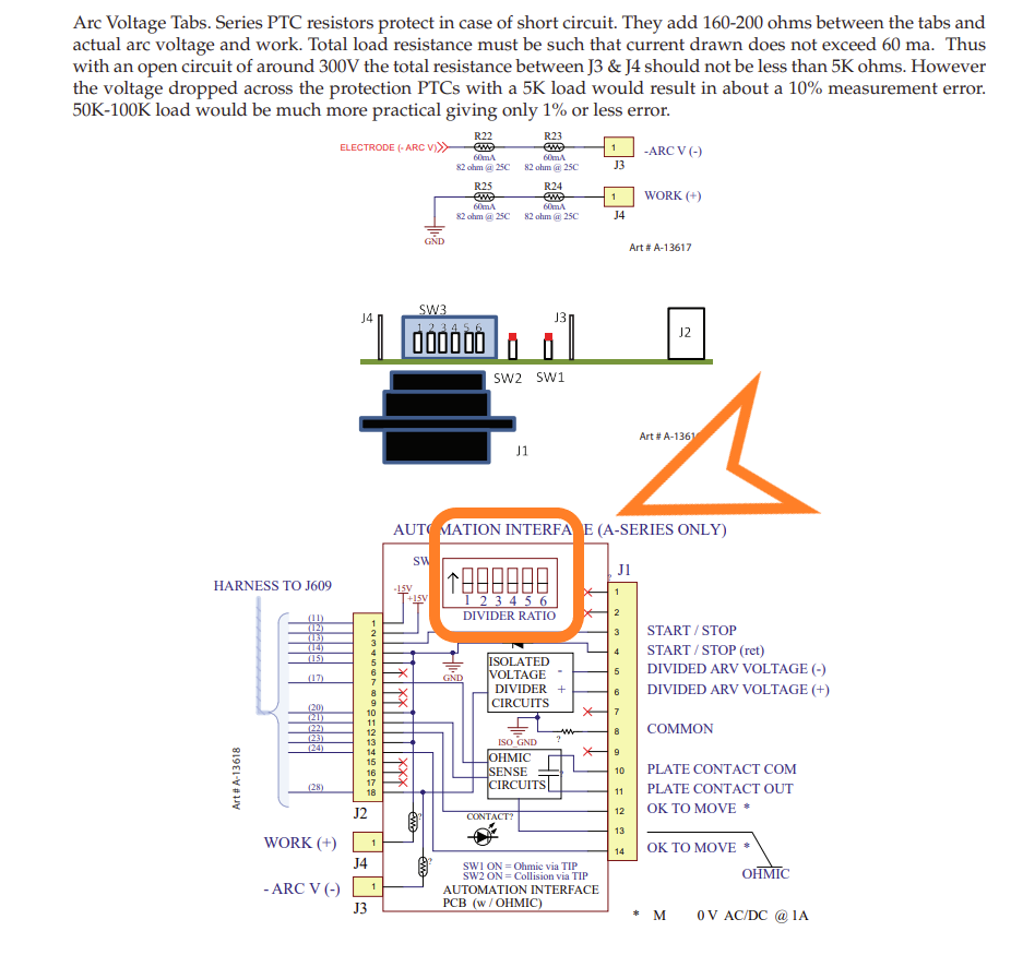
Here are a few clips
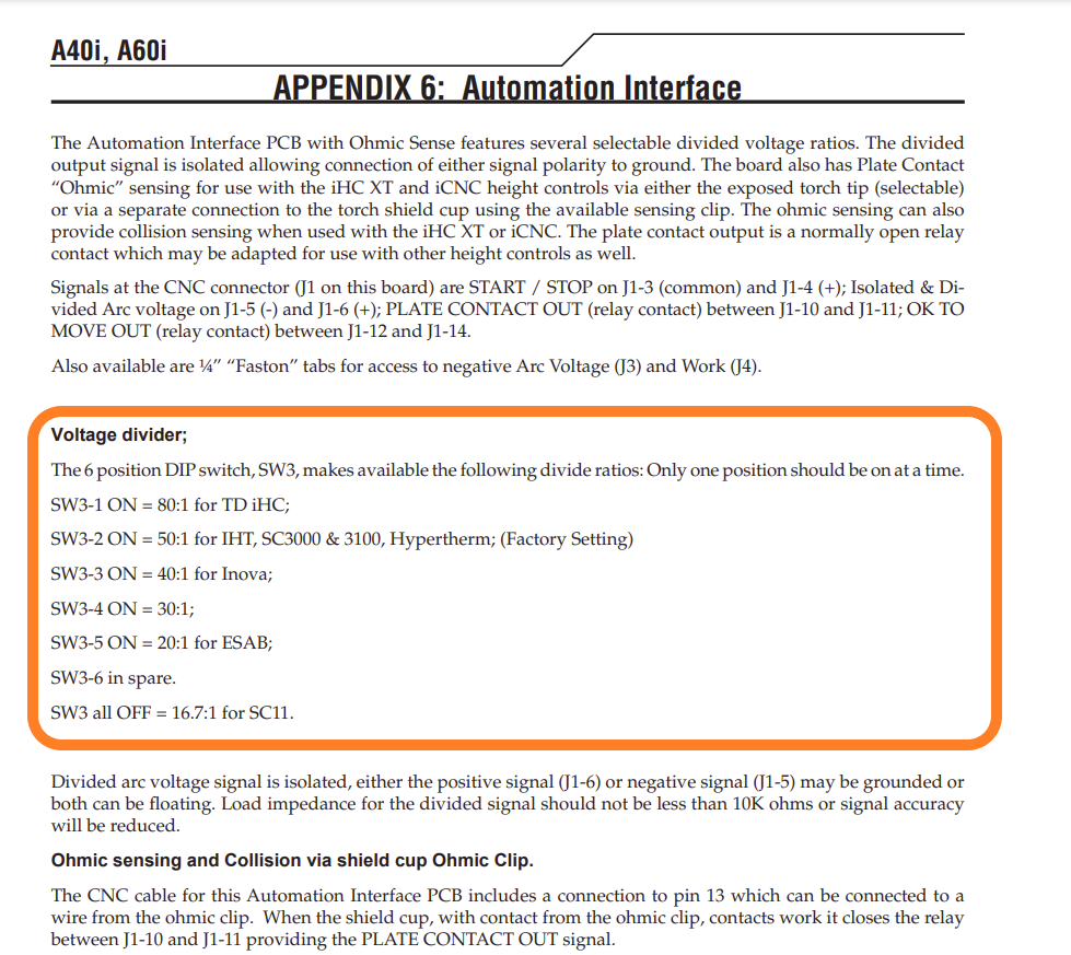
. Appears to be factory set for 50:1 divided voltage.
1 Like
Thank you for that TinWhisper from what I see switch 2 should be on to achieve a 50:1 ratio.
you’re very welcome.
Yes and it’s also the factory setting.
So unless someone has changed it for some reason it natively should be ON for dip switch 2 and in the correct position for you to start using.
I bought a 60i to go with the XR I have coming. Came from IOC via eBay. I bought the Automation Interface Kit - 9-8308 card from Bakergas.com. I installed it myself in 30 mins.
1 Like
I went to raw voltage to get going cnc card won’t be here for 2 weeks but everything is hooked up to 60ix per Langmuir instructions lights are on in cabinet as they should after putting in the LS-THC im running windows 10 on the computer it’s a brand new HP picked out by a IT guy per Langmuir requirements and it did update when hooked up but it won’t automatically connect and it won’t let me manually connect to height controller in fire control.
How did you hook up your polarity?
It won’t sense it if you have the polarity reversed.
I hooked red right on the back of the clamp inside the cutter and the black right on the big nut of the torch supposed to be negative
Sounds okay, you have a constant current electrode positive machine.
And then from the vim module it’s PV output to your langmuir electronics box?
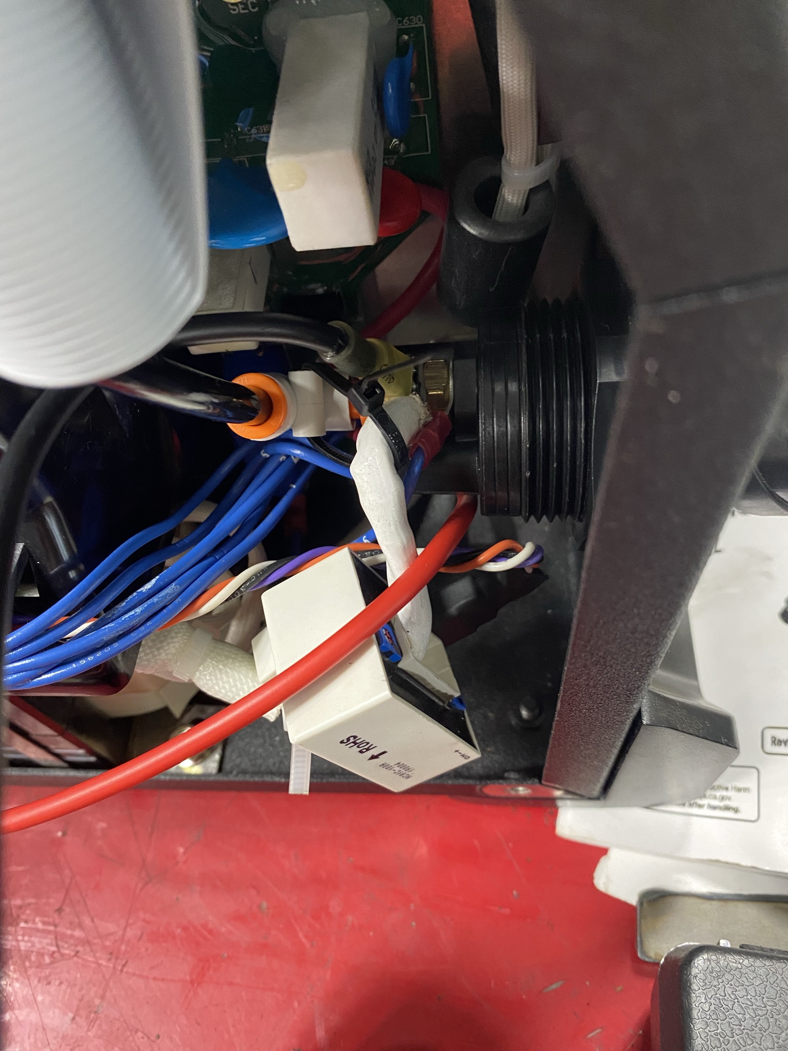
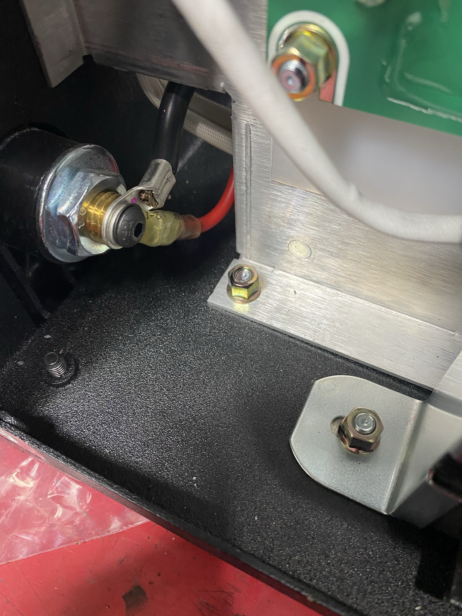
This is where I hooked up TinWhisper please let me know if I should do It different. And I am hooked to the PV output. The top picture is showing the black wire that I hooked to the torch and the 2nd pic is of the red wire going to the clamp. My wires are the ones with the yellow heat shrink ends on them. Thank you for you time it is appreciated.
This is where I hooked up but I have a resting voltage of 12.4 and after following the flow chart it says I have something hooked wrong. Anyone have pics of where they hooked for raw voltage on a 60ix?
I have a hard time telling what you have going on there .
I’ll take a look at the diagram for the other one model.
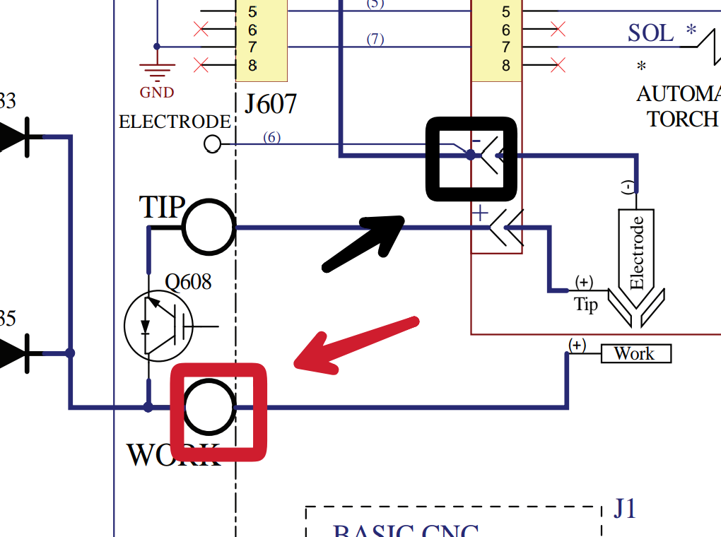
it sounds like to me that you have it hooked to your pilot Arc and work ground.
No the pilot is right below where I hooked up.
It looks right from the picture I can see wire six from the electrode coming off that terminal and then I can see that white wire with the fiberglass insulation running through the hall effect sensor(it’s that white square it’s basically a current clamp to measure current through induction) so it looks correct from the picture. Couldn’t see it very well before I was trying to do it on my phone just got home to my desktop.
I checked into the diagram too it’s exactly the same besides for the addition of the automatic interface circuit board which comes on the other model.
That resting voltage does seem high?
Have you unplugged your IHS and tried the THC test again?
Yes I did and it still failed
https://www.langmuirsystems.com/thc/guide
If you’ve gone through both guides and
it really does appear to be hooked up correctly ( someone else who actually owns one of these machines could confirm)
So, I’m not quite sure where to go from here.
Ok thank you for your help.
1 Like