THC Wiring: color of wires confusing

Oh I see it now. The first picture is from the directions for the cnc port. Thanks Daniel!

OST…for future reference

I’ve read this reply, but still don’t understand the reasoning behind the Div Voltage Input Cable having positive and negative reversed from traditional red/black positive/negative wiring on any other electrical wiring I’ve done.

I understand the directions. I don’t understand why it’s reversed. I read it 10 times. Understood the directions and muscle memory kicked in. Then I looked at the diagram I posted and realized I did the opposite and now need to fix my diagram and my pin placement. Fortunately I caught it before firing the plasma cutter.

Because your plasma cutter has them reversed from most other appliances. The work clamp or “ground” is actually the positive connection. The torch is negative. People call the work clamp the ground but that’s not the correct term.

But I’m wiring positive and negative to pin 5 and pin 6. I understand where they go, but if I want negative to pin 5 and positive to pin 6, black to 5 and red to 6 is what I did and would do. It’s confusing.

Yeah, it’s just easier to follow the instructions - they’re all that matter :grin:

I was not aware that the clamp was positive until I was reading the instructions and did a little head scratching. Off topic question, if I have my welder and plasma cutter both clamped to my welding table will it blow something in one of the devices? so far hasn’t been an issue because I only have one outlet, but I’m in the process of adding another one so both can be plugged in at the same time.

You want the plasma clamp on the Crossfire or better yet, the material you’re cutting. It’s okay if one side of the clamp is in the water. You want the shortest, most direct path between the plasma’s work clamp and the torch tip so you get & maintain the best arc possible. You don’t want the plasma clamped to your welding table unless you’re hand cutting with the plasma something that is on (or supported by) the welding table.

I wouldn’t keep both clamped to the table - too much variability in the design & construction of welders of various types over the past 10 or 15 years to be able to safely predict the effect of one’s electrical fields with the other.

image image Here’s what I did for my wiring of the THC module red & black banana wires for the Early Razorcut45 plasma cutter WITHOUT the CNC plug.

I will Stress if your not comfortable with electronics or electrical to seek assistance from a professional or someone familiar with electrical wiring!

I have a 20 + year backround in Automotive technology and I taught advance electronics and technology.

This is basics wiring but these lines are very HIGH VOLTAGE wires!

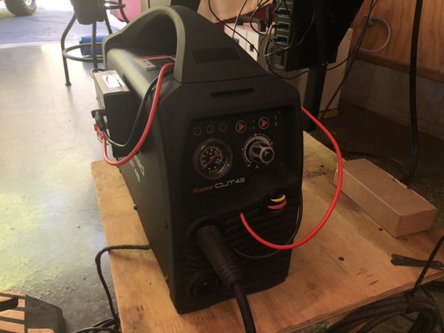
This is a representation of how I wired mine.
To get it to work properly for me!
On my RAZORCUT45 , early machine , without the CNC Ports.

If your have any doubts you should seek professional assistance!!

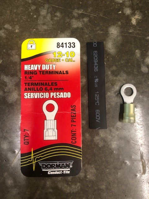
I used 600V shrink tube. Heavy duty 10-12 Ga. circle :o: ring connectors crimped onto the red & Black pig tails from the THC Module.-(Banana plugs wires)
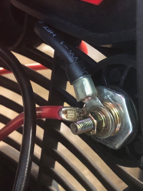
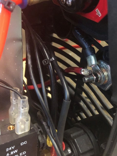
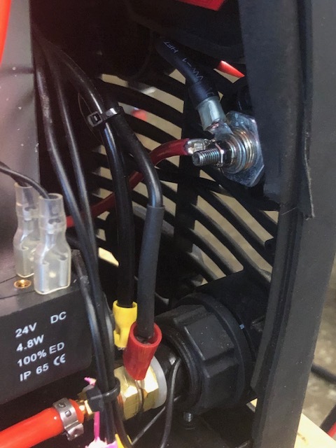
Red lead to the ground /Clamp…stud. Inside your machine.( This machine is the original RAZOR CUT 45 1st offering from Langmuir without CNC Ports) the small nut was 9mm
Inside & the bolt is an Allen bolt accessible through the front of the ground clamp port with the barrel end removed . Think it was 5mm Allen wrench that fit . The 9mm nut is really tight! So holding from the outside with the Allen was necessary to loosen it.

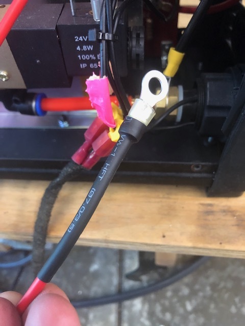
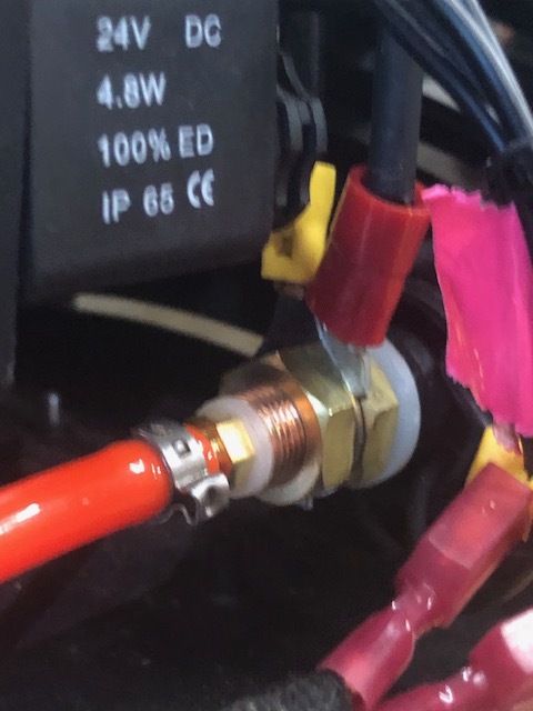
Black to the black torch stud which is a large 5/8” + O-ring Terminal that’s on your Torch stud inside the machine , this one has your air supply fittings on it as well. The nut was an 18mm .

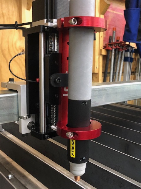
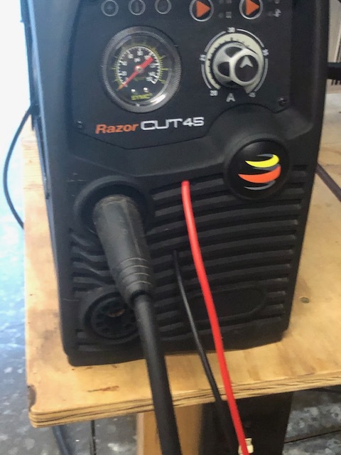
Ran both out the front slots in the Face of the PLASMA CUTTER

:+1::wink:

1 Like

@PWCNC This is super helpful! If you wouldn’t mind making a new post on the THC forum (https://forum.langmuirsystems.com/c/ls-thc) by copy and pasting this comment we will sticky it to the top!

Nice and clean. I know how it makes you twitch putting the red wire on the black wire connector inside the machine but you gotta deal with what the plasma folks decided to do (a lot like old British 6V positive ground cars :smiley: )

Ok will do

1 Like

Did it twice by accident,:man_shrugging:
But it’s there.

I was with BMW 20+ years.
Got to do schooling on their electric hybrids and hydrogen regen cars in development.
Seeing all the Warning High voltage! And Death stickers everywhere brings back memories, and the mythological step by step working procedures during repairs on theses vehicles was engraved in your brain by the time they were finished!
It didn’t really take off till after I left BMW in 2008.
But then I taught advanced technologies at NTI . For 4+ years after that …
ohms law applies everywhere in every facet in one way or another especially in plasma cutters.
I miss the classroom and the fresh impressionable minds you got a chance to help mold into professional technicians…
Arc voltages is easy enough to relate to spark plugs and plug gap settings to put it in its simplest form for discussion. :+1:

1 Like

Necro thread bump. Just wanted to point out that it’s not just the divider that uses a reversed wiring color scheme. Inside the control cabinet the positive DC wires from the power supply are black and negative are white. It’s a catastrophe waiting to happen if someone goes to troubleshoot their machine with conventional wiring colors being red positive, black negative for DC. I mean, if you’re going to use white and black, at least still use black for negative.

Just a thought I’m contemplating as I prepare to install a replacement power supply for the DOA one that came in my controller. An easy task, made tiniest bit less easy because I have to remember to wire it “backwards” once it gets here.

1 Like

you could mark the white cable and the spot where it goes on the plastic cover with a - so you know where it goes.

Don’t get me wrong, it wasn’t hard to swap out the power supply, I’ve taken DC electronics classes, and am currently playing around with a little one axis test box I made to test steppers up to 4A @48V with an arduino loaded with Grbl for some other projects I’m working on. It’s just weird that they wired everything with the colors “backwards.” It’ll be someone troubleshooting late at night who forgot to reference their “before” pictures and started hooking their wires back up that makes the mistake.

I wanted to check on this with an Electrician.

The difference that you are seeing is way wiring is handled in the electronics world and in the commercial electric work.

What I grew up with in Technology is the same as you. Red wires are hot and Black is ground. For the longest time I thought that this was the standard. However…

An electrician by code will wire Black as hot, white is neutral, Green is ground. If there is a Red then it is a secondary hot.

It appears that the torch was laid out to be familiar to an electrician that would be connecting it to building wiring. Hence the adherence to the electricians wiring colors. Use the presence of a Green wire to tip you off or the lack of a Red wire in this case. In any case, a DVM is your friend. Test before you touch.

I never had an issue with how the power supply was wired to AC, my issue is the DC wiring. AC color code standards are not DC wiring standards. To be fair, there isn’t necessarily a “standard” of red(+) and black(-) in DC wiring in the US or by IEC Code. However it is the most commonly used wiring scheme for ungrounded DC circuits in electronics.

Take a look at the related DC standards and recommendations in the following link and about the only wiring color scheme you DON’T see listed for DC is black(+) and white(-).

I’m not trying to start an internet fight, nor am I going to explain any further. No one in their right mind sees white and black DC wires and assumes black is positive. That alone should have been enough of a reason to adhere to some actual standard or common practice people could look up if they are ignorant in DC circuits.

1 Like

Any pointers how to take it apart? I took all the screws off from it but wouldn’t come apart. I don’t want to break anything.