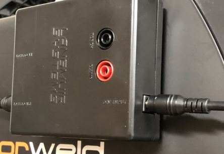
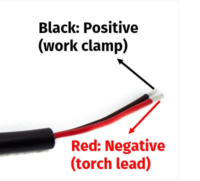
I was looking through the install instruction for the THC and they have the red as negative (torch lead) and black as positive (clamp), but on the same pigtail the end that plugs into the box the box is labeled (red) clamp and (black) torch. This is pretty confusing, why not use the same color to polarity on both ends?
It doesn’t say which way the colors go. Red usually being positive and black negative. Red goes to your clamp post black goes to the torch post. Your ground clamp is positive not negative.
Just to specify for those with a Hypertherm 45XP with CPC, the LS THC is wired:
LS THC Red to Hypertherm Black (CPC Port 5)
LS THC Black to Hypertherm White (CPC Port 6)


This is what I’m referring to.
Thanks for the info, it will help when hooking it up.
Instructions:
“Cut the blue wire
after the red wire!”

You’re right that is confusing, I would not hook it up that way. Someone is going to mess that up.
I know they don’t want responsibility for people opening up machines. But you would think with the use of the older razorwelds they would have an actual wiring diagram for us.
That was my thoughts exactly. I had to read it three or four times and it still didn’t make sense why they would do it that way. If I had the machine in front of me I would have screwed it up because I’m inpatient and who needs the stinking manual anyways. Would have been an expensive mistake, and down time waiting for replacement parts.
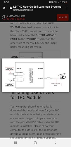
And in this the have the red box around the clamp and the black box around the torch. Like it should be.
That is what worries me about using an older machine with limited documentation. I will lean heavily on the forum for help.
There are two seperate strategies for wiring the voltage input module (VIM). The strategy you select depends on the plasma cutter that you have.
If you have a plasma cutter equipped with a CNC port, you’ll use the Divided Volage Input Pigtail Cable that is provided. The male plug connects to the ‘Div’ input female plug on the side of the VIM. The red wire in the pigtail connects to the negative terminal on the CNC port and the black wire connects to the positive terminal on the CNC port. You’ll need to source your own terminal connectors for the bare wire ends depending on how the connections are made on the CNC port.
If your plasma cutter does not have a CNC port, then you will need to use the Raw Voltage Pigtail Cables that are provided. The plug on the black cable will plug into the port labeled ‘Torch’ on the VIM. It will need to splice into the torch lug inside or outside of the plasma cutter. The plug on the red cable will plug into the port labeled ‘Clamp’ and will need to splice into the work clamp lug inside or outside of the plasma cutter.
I think the confusion may be stemming from the fact that the wire colors are not the same for each strategy. Since only one strategy is only ever used, it should not be an issue. We could have opted to create a ‘Quick Start’ guide for the THC system but we decided against it because it is very important to us that people understand completely how to setup and use this system. All of the information for this product can be found in the User Guide and customers will need to read the guides in order to be successful.
If you purchased a Razorweld Razorcut 45 with CNC port, then none of this applies to you. Instead you will use the cable provided with your plasma cutter to connect directly to the VIM.
Oh I see it now. The first picture is from the directions for the cnc port. Thanks Daniel!
OST…for future reference
I’ve read this reply, but still don’t understand the reasoning behind the Div Voltage Input Cable having positive and negative reversed from traditional red/black positive/negative wiring on any other electrical wiring I’ve done.
I understand the directions. I don’t understand why it’s reversed. I read it 10 times. Understood the directions and muscle memory kicked in. Then I looked at the diagram I posted and realized I did the opposite and now need to fix my diagram and my pin placement. Fortunately I caught it before firing the plasma cutter.
Because your plasma cutter has them reversed from most other appliances. The work clamp or “ground” is actually the positive connection. The torch is negative. People call the work clamp the ground but that’s not the correct term.
But I’m wiring positive and negative to pin 5 and pin 6. I understand where they go, but if I want negative to pin 5 and positive to pin 6, black to 5 and red to 6 is what I did and would do. It’s confusing.
Yeah, it’s just easier to follow the instructions - they’re all that matter 
I was not aware that the clamp was positive until I was reading the instructions and did a little head scratching. Off topic question, if I have my welder and plasma cutter both clamped to my welding table will it blow something in one of the devices? so far hasn’t been an issue because I only have one outlet, but I’m in the process of adding another one so both can be plugged in at the same time.
You want the plasma clamp on the Crossfire or better yet, the material you’re cutting. It’s okay if one side of the clamp is in the water. You want the shortest, most direct path between the plasma’s work clamp and the torch tip so you get & maintain the best arc possible. You don’t want the plasma clamped to your welding table unless you’re hand cutting with the plasma something that is on (or supported by) the welding table.
I wouldn’t keep both clamped to the table - too much variability in the design & construction of welders of various types over the past 10 or 15 years to be able to safely predict the effect of one’s electrical fields with the other.
