Search EBay usb. Mach 3
Ouch! Mine shipped from buildyourcnc.com already $89.99
Wow, these guys turn a really healthy profit. 
1 Like
is there a link to an ebay site for that longer ribbon cable for the THC display to motherboard?
https://www.amazon.com/gp/product/B07FZWBP78 you can cut these to length and then crimp an IDC connector to the free end with these: https://www.amazon.com/gp/product/B07DVXXW4Y
Cool! …Thanks!
can someone help me understand the need for two breakout boards and the two separate power sources? is the one power source and bob circled in red is that the cross fire unit?
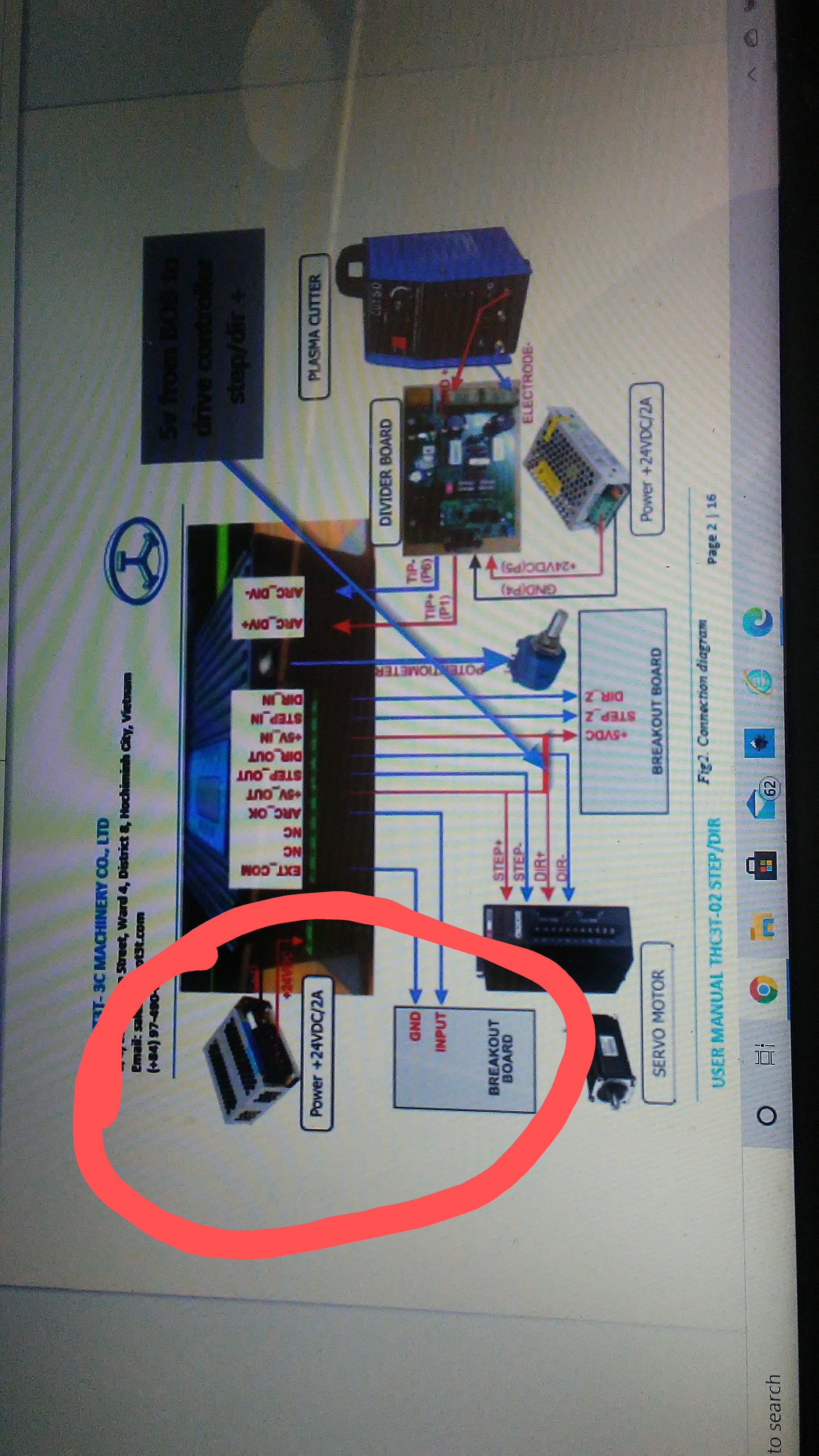
It might be better if you cite the original link so we can actually see what the objects are. I know how to wire in THC and I can not answer your question with the attached photo.
it was back up this page midway. it was Dicky that had posted a link comment #30
Ah, ok. It was from @Dicky 's write up doc that he posted. That was a very useful document, but it was more a ‘documentary’ than something to be taken literally. What power supplies you need depend on how you’re going to modify your CF controller, add in the THT03 controller, and assorted other hardware.
At a minimum you will need 24V DC to power your THT03 controller. Several people have stepped down the 36V power supply in the CF controller, but that gives you no isolation between the systems and puts more load on that key PS.
Further, some have built on to the 5V supply in the CF controller, but that is powered by your computer’s USB port. IMO, a very bad idea.
I think, given the signal sources on the CF controller, it is very difficult to avoid using the CF controller’s 5V supply for the local stepper motor signals, but the OUTx signals, the INPUTx signals, can and should be driven from an isolated source. I have a separate 24V supply for the THT03 because I don’t want the voltages in that domain to come anywhere near my laptop’s USB port. I have a separate 5V supply for the OUTx and INPUTx signals for the same reason. My Z stepper drive is on the same 36V stepper as the other steppers (mainly because I have the current set at 1.5A which is within the 36V PS budget), but the inputs are driven by the THT03 board and my isolated 5V PS.
Torch relays, etc, etc, can be driven from the sources that fit these other requirements. In my case I am very happy with the original relay they chose (circa Dec. 2019) because it’s fast and handles enough current to trigger my PC. It may not drive all PCs and may need to be upgraded to a heftier relay.
I hope that helps… 
I can personally attest to this as accurate information. I purchased a proma 150 and it will illuminate arc ok, up, and down in the diagnostics menu but it will not control the z axis for torch height control.
I’m updating from a Hypertherm Powermax 30 to a Powermax 45XP with the CPC port. My question revolves around the 50:1 divider board supplied by Robot for the THC3T-02. My PM30 needed to be wired directly from the output to the raw divider IN, but the PM45XP has an internal 50:1 at the CPC port. The ROBOT divider has an “EXT” setting which would seem to accept that, but do I even need ROBOT’s divider at all? Will the output from the PM45XP not be good enough alone running straight to the THC3T-02?
I don’t know the answer. It seems as if a direct 50:1 connection would work, however, having used the THC3T-02 with a 1:1 connection and observing other’s experience with alternatives, I think the Robot divider board is much more than a simple voltage divider. Given the electronic parts on the board and the performance, I would say there is a very healthy and effective filter system in that implementation and, as a result, noise and other anomalies are handled very well.
The only downside of the divider board is it’s size. It’s probably twice (or more) the area of the the THC3T itself and you need to find a way to package that. You might pose the question to Robot, they’ve been responsive to my questions.
Thanks for the quick reply. I think you might have a point as far as the signal filtering that I hadn’t considered. My old RS-232 cable already hooks up to the divider, so I think I’ll keep it in the circuit just to be safe. Now that I think about it, why would you provide a 24V box that does nothing in the EXT setting?
1 Like
Just wanted to say thanks for the info and wiring diagrams. I am in the process of upgrading mine with Z axis and sensors, bought the red replacement board from amazon.
Anyway sometimes it’s not as simple as it should be. I used the cheaper sensors from amazon, I could not get them to work on input 1 the digitize light stayed lit even when I un hooked them, finally after trouble shooting and not coming up with anything I switched to input 4 and bingo it worked on the test bench. Installed them today on the machine and one of the sensors was bad, it kinda had a mind of it’s own and even when it was off and about an 1-1/2 above work the digitize light would flicker finally completly un hooked it running just two sensors it works with no problems
1 Like
Well, on the plus side, if you do DIY, then you HAVE to learn how it works and you WILL be able to fix/adjust/tune it.
DAMHIKT!
2 Likes
Yep for sure. That was one of the reasons I went with the small table, I new zilch about them and Cad . At work they had bough a 5’x10’ Burntables brand table with Auto Cut 300 XT plasma cutter . That was 5 or 6 years ago and the guys that supposedly new how to run them had ordered this combo, One of the guys put a torch on the table and played with it a bit but never got it going and made a mess out of the software . Both guys quit and left and the tables been sitting . Ended up in my lap and what a steep learning curve this has been. Anyway that one is working without THC so my plan is to upgrade and simplify it and if that’s not enough in the mean time they bought a Messer [ I think that is the brand ] industrial table, it is about 8’ wide by 20’ long from an auction so I have to get that one going also .
1 Like
Success I got my replacement sensors in today and swapped out the bad one, switched back to the WIN 10 PC and bingo it works great. One of the things I did different was P and D outputs to stepper drivers I reversed it and went to P+ D+ with the P- D- to ground outputs then the plan is to hook up 5 volt power supply to the 5 volt pin and remove the chip so as not to use power from USB. Next on the to do list is make a bigger controller box to house 3 power supplies with the 4 relay board and with the 4th axis stepper driver
Thought I would mention been working on the Messer table, put in the same USB BOB so its basically the same setup just bigger anyway installed a Proma 150 SD and when firing up the system the Z motor would grind and make all kinds of racket with no plasma hooked up yet, bypassed the Proma and the Z worked fine, spent hours trouble shooting thinkin I messed up somewhere, finally I gave up and called Eagle Plasma the out fit I bought the Proma’s from explained my problem and they helped me out pretty quick I had it wired like tool junky shows with the 24 volt feeding the Proma step and dir to Proma then step and dir to stepper driver but I had used ground from the 5 volt side on the BOB to the driver, well that was the problem on this one I had to connect a ground jumper from the 24 volt power supply to the 5 volt ground side and then the system worked as it should
hi
i work the same sketch like you
i have problem with z axis and thc 150, i can see the lights turvh on,up,down are working in mach3 diagnostic but i have no move to z axis
i have enable the allow thc control and i also enable the thc on up down
have you any idea what is the problem?
@ciric when did you buy your table…and is it the Pro table or the old OG table?