Is is there any technical reason why it wouldn’t be possible to temporarily detach and rotate the Y gantry (around the Z axis), so that the spindle faces the back of the machine?
If the MR-1 can be run in this configuration, I’m thinking one could embed a secondary fixture plate outside the normal work table area (during the concrete pour), and then surface it parallel to the primary fixture plate.
Then, the secondary fixture plate could be used to mount a 4th axis rotary table or tailstock, and the machine could go be reassembled back to the right-way-around configuration.
Thoughts from Langmuir on this? I’ve attached a screenshot to describe what I’m interested in doing.
That is good info. I already had a 3rd fixture plate add to my order for this reason. Was shown it will almost fit just need a indentation machined to clear the cable support bar.
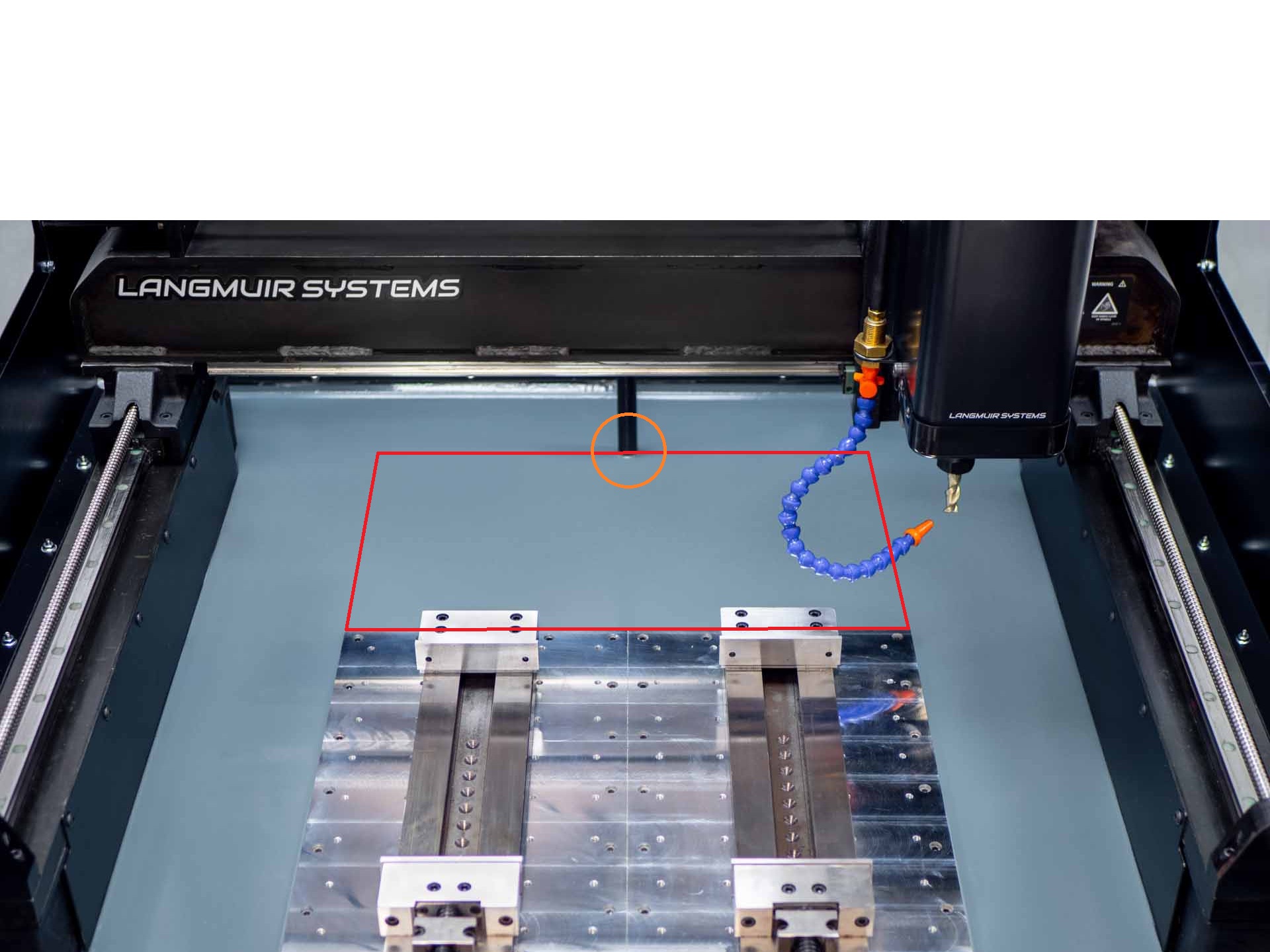
By the way, it looks like a Tormach Microarc 4th axis may be able to fit far enough rearward that it’s out of danger of collision with the spindle mount, while the face of the chuck is still in (or abutting) the work area.
Or, 0.25 inch spacer plates under the X gantry mounts would probably do the trick as well. Yes, I know that tormach’s unit is half the base price of the whole machine It’s probably worth it to me anyway, if I can avoid traditional setups for some smaller parts.
Any chance someone from Langmuir could post a plan + elevation view of the machine? Even a simplified wireframe would help enormously.
Provided that you’re not holding stock wider than about 3.5" inches in the jaws, anyway
As an aside, I found some cast-in-place stainless steel anchors that seem like a possible good match for the application, if one wants to use a non-Langmuir rear base plate. Not sure if Langmuir sells theirs or if they’re a commercial/off the shelf part. 4-6 of these with 4800lbs max pull out load should be pretty damn secure I think.
@langmuir-daniel is it possible you can give dimensions of machinable area with the gantry flipped in relation to the y axis rails? I’d like to get a plate made up this week so I can pour this weekend. Would it be the same at the normal base plate? roughly up to the Y axis pedestals?
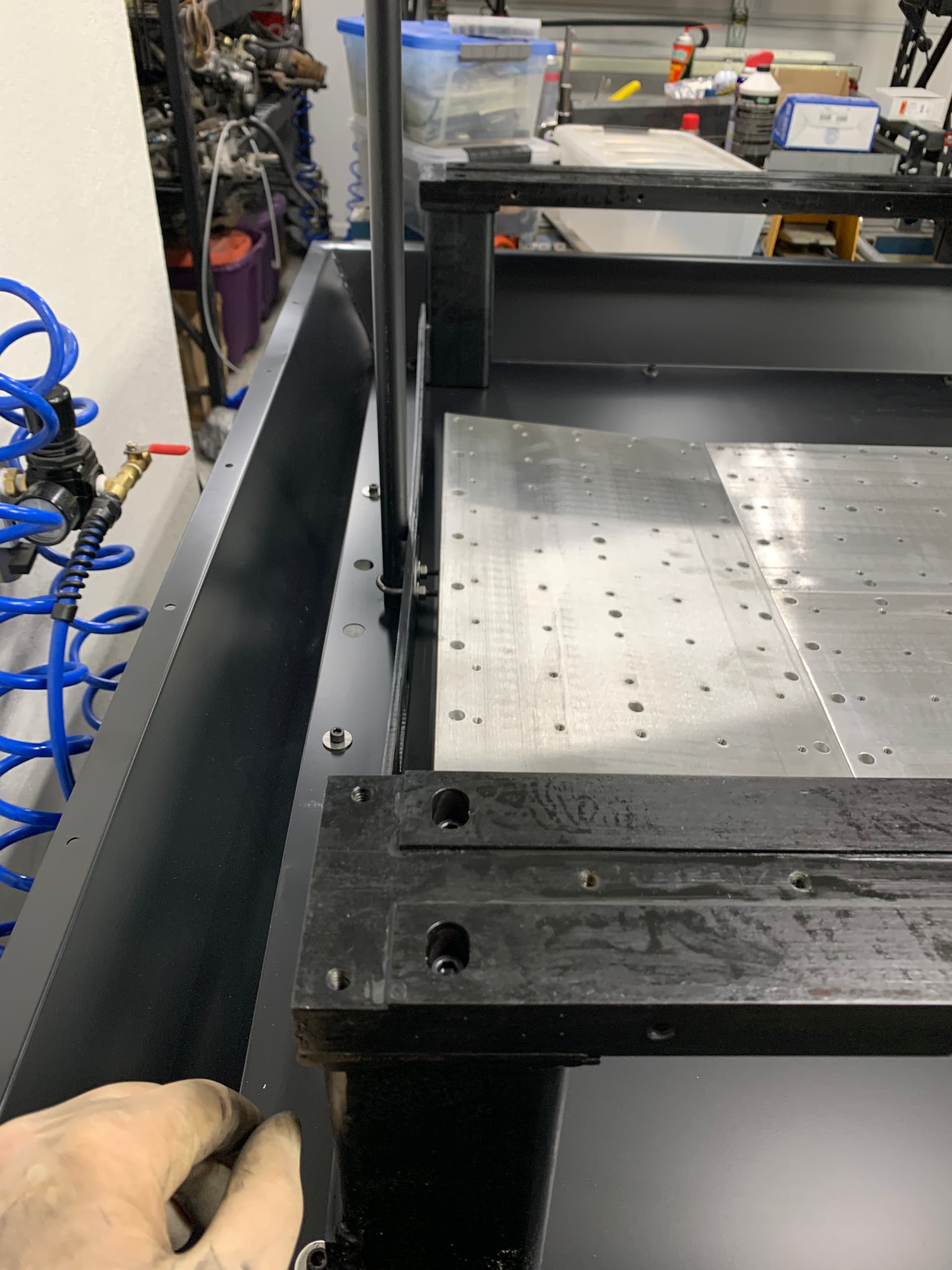
I picked up a 8" deep 22" wide 3/4" thick 6061 plate this morning at the surplus yard (since I was there) which I can use (with some trimming) to extend the supplied baseplate, but I have no idea if that is not wide enough or too wide until Langmuir (or someone with a built machine) does a few measurements. All it would take I think is to mark the Y spindle center at it’s maximum Y travel, and then measure spindle center to center of Y gantry and add them together to determine the maximum Y spindle center if flipped. From there its easy to figure out how far Y cutting could go, but it’s harder without an assembled machine.
@MikeJ Your plate looks to be pretty much perfect I think, even if the normal work area doesn’t extend forward of the Y rail support columns. See diagram.
There is however the question of the Cable Support Tube, since it looks like it might be possible to crash into it with the spindle body cover. Maybe it could be relocated further back, or temporarily removed during the surfacing op.
On thing that needs to be accounted for is the cable support tube. I purchase a 3rd plate from Langmuir but was told it would need to get a relief cut to clear the support tube. This will also be the case but ever more important to make sure the z carriage does not contact the pole. I am thinking of modifying the pole so it could be removed?
That 3rd plate from Langmuir is 10" wide I think, so 2" wider than the one I am thinking, so close to the edge of reach.
Many thanks for laying that out Amostdudley, its appreciated! I was going to butt the 3rd cross plate against the two supplied by Langmuir (like you drew but tight against) and then use some light angle and the tapped hold downs to hold all three plates as planar as possible, as well as use a similar concrete anchoring system on the new plate as the two supplied plates. I had not thought about leaving a space between the plates, but that is totally possible … hmmm.
I also am planning on installing an array of coupling nuts with cap screws submerged into the concrete (*the same as used on the supplied plate), with the top of the coupling nut planar with the large plates to provide anchors outside the work surface - it may require some hand grinding once the main plate is surfaced to make them all planar, but I want enough anchors in the work surface to hold larger pieces in place. They would run in lines both on the X and Y axis. Right now, if your piece is larger than the work surface, you are out of luck unless you have some through holes.
Like you, I am trying to make sure everything I want is in place since it will be a bear to do it once the concrete is poured. It is possible (I am an ex-contractor and cut a lot of concrete in my time) but painful.
Not sure about the cable support yet … I have not gotten far enough to even know how its attached, but of course its only metal – so modifiable!
Given the option of flipping the gantry to accommodate a larger work area, it would be awesome if Langmuir offered working holding plates that were 10” longer than the existing ones as an option. As far as the cable management boom goes I was just going to fab a mounting plate for it with drilled and tapped holes and cement it in. That way the boom could be removable. With the option of flipping the gantry a guy could just push that boom mounting plate a bit further back perhaps.
Just want to clarify, I was only proposing to flip the gantry as a one off operation. I expect that doing so could introduce some angular error that would need to be adjusted for each time.
So I doubt this is useful for creating a larger “work area”, but I’m hoping mainly to do this just to create a larger fixturing surface. Sorry if I’m being pedantic!
That was my understanding right from the beginning - I am just looking for more options to mount stuff before the concrete is done - I appreciate your ideas! .