if you look at the video about the “no RnR motion control error”, he addresses the issue about the 5V and modifying the BOB.
That additional power supply is dual voltage 24V/5V.
if you look at the video about the “no RnR motion control error”, he addresses the issue about the 5V and modifying the BOB.
That additional power supply is dual voltage 24V/5V.
I paid 38 on amazon, I found cheaper ones but shipping time was much longer than prime.
Yes it is, hooked it up to power today and it does put out 24v and 5v, haven’t seen those before, I may get another one like that to power led lights in my powder coating booth when I rebuild it.
i guess i got lucky and found one that had PRIME 1 day also.
Guess I missed that one. lol
If you don’t supply 24v (something over 5, I believe a guy on here said it’s at about 11.5v) then the inputs on the breakout board do not function. So you can add limit switches and everything else, but it’s like the board is deaf to the signals coming from them until the 24v pin has the power it needs… for the stock langmuir set up, the inputs are not needed…
I added the limit switches on the Langmuir board today and it works great so far.
Do they add about 1/2 inch of travel after it homes? If so I found where to change the settings on that…
Open the crossfire xml file with wordpad, then scroll all the way to the bottom and look for , , and . They should read .500
I changed mine to read .05 on the X and Y since I only have limit switches and now it only goes a smidge off the switch once it finishes it’s homing sequence… this is now your MACHINE COORDS.
Yes, it does exactly that and I have spent about an hour looking where to change that number and now you tell me where to change it before I even ask. You must be psychic? lol
Thanks.
lol… i actually attached a video on the other thread on how to add code to the REF ALL button but that was just a work around. but that wasn’t true MACHINE COORDS.
So i kept digging and decided to look in the crossfile xml and went thru the whole thing until i found it at the very bottom.
Would you happen to have a link to that video handy? I’m taking my laptop with me tonight hoping that I’ll have time to mess with it some.
Thanks
here ya go.
keep in mind, that video one was just a “band-aid” fix until i found out modifying the crossfire xml file lets you adjust that 1/2 inch gap without adding code and it’s true Machine Coordinates which will show 0.00 in the DRO’s for machine coords. I would use 1 or the other, not both.
when i first added the code to the REF ALL button as shown in the video, i went -.48 on both the X and Y lines to close that gap as far as possible without it triggering the switch again. but then if you click on the MACHINE COORDS button, it’s gonna show -.48 on the DRO’s instead of 0.00 because it’s not true machine coords.
Great video for more knowledge about what can be done with the program.
I believe that I should be able to do what I want modifying the xlm file.
What I want it to do is basically go up about 2 inches and over about 2,5 inches for the home position that way I don’t have to jog it there and write down the offset numbers in case it crashes into a tip up. From the sons of what you’re describing in the xlm file, I should be able to change the .5 to the 2 and 2.5 that I want.
Thank you.
Yeah I’m sure there is a setting within mach3 where you can change that but I couldn’t find it… and with the table being so small, I couldn’t just let it take away .5 inches from each side… that’s a lot of real estate for a small table.
I understand that, but with my current setup I can afford to lose it and it will be quicker if I have to recover from a crash.
Well that isn’t going to happen tonight with this schedule. LOL
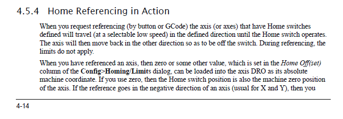
From the mach 3 manual… If home is .5 inches off the home switch, value the DRO at .5, but I think 0,0 will trip a limit… So value it at .6, this would give you .1" off the limit switch…
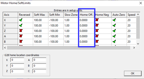
From what I saw the other day when I got my limit switches working, the only thing that the highlighted boxes did was change what showed in the DRO when it finished and was sitting @ .5 inches from the limit switch. I tried setting the offset to the 2inches that I wanted it to go to but all that it did was sit at the .5 inch off of the limit switch and showed 2.000 in the DRO.
I’m not 100% certain but I think that if you set the value at .400 and sent it to the zero then you should have .100 from the limit. at least that is what I think happened to me when I tried it. but when it was on 2.000 and I sent it home, well it crashed into the limit trying to go the 2.000 that it was set at.
because you don’t have 2 inches to home… so your trying to go 1.5 inches past the home position so it will crash… I know I read somewhere how to set the “back off” distance, just cant find it at the moment… You didn’t have to edit the xml file, but it that works, then it works… More than one way to skin a cat!
You are correct, I was hoping that by setting the offset that it would go to the 2 inch that I wanted it to but as you know, it didn’t. It seems that I learn more about what doesn’t work than what does work most of the time but I sure have fun trying.
I would like to find the back off setting but for now I will mod the xml file.
Thank you
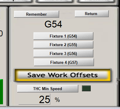
I have never ran a CNC machine that let you tell it where to go to after homing… home is home… But I do believe that you have use one of the G54, G55, etc… To set up a permanent offset to accomplish this… I have never used it but… Typically in mach3 for what it is being used for in langmuir, you only use g54. But you could setup G55 to always have your 2" off set from home position, so when you go into that alignment, you would be at -2,-2… Someone else will have to chime in, like I said, I don’t use it, have never used it…