Today, I cut some simple exhaust flanges, two of the holes are 0.5" holes, and were drawn that way in Fusion. During toolpath generation, I used 0.060" kerf for the 1/4" plate being cut. The hole size came out at 0.45XX", so I adjusted kerf to 0.055", and then again to 0.050", and each time the hole size still came out to 0.45XX" diameter. Each time, I started with a new nozzle and electrode. Same air pressure. Same amperage. Same machine. Same everything. I am very confused and extremely frustrated, as I ended-up having to destroy two drillbits to ream out all the parts that I cut today.
To eliminate the simple solutions:
Yes, i changed the tool parameters.
Yes, i regenerated my toolpaths.
Yes, i regenerated the post file.
Yes, i loaded the updated post.
What could be causing this issue???
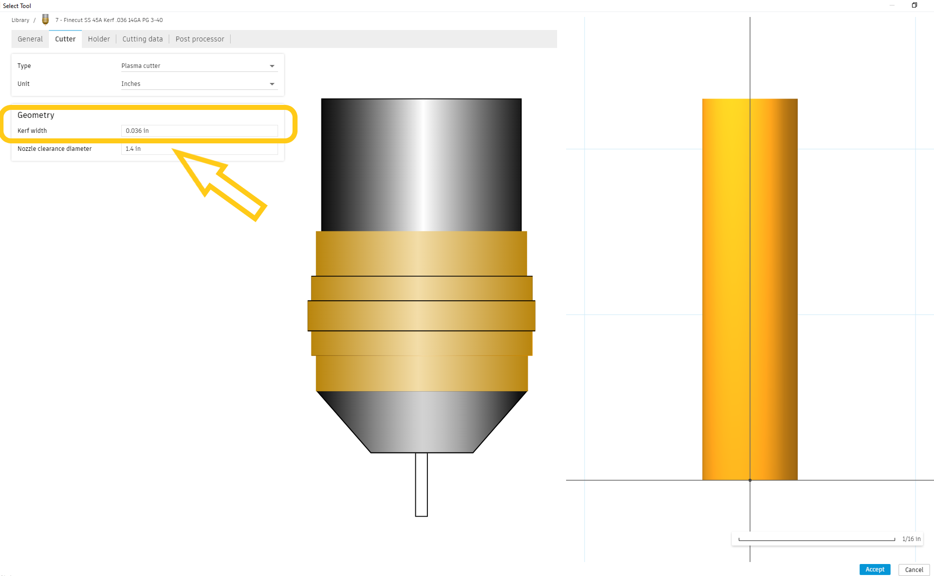
If I change the kerf width calibration,
the hole size should change, right!?!
Thank you in advance for any help
or suggestions you might have!!!
P.S.
I’m not really sure if this is a CrossfirePRO issue, or a Razorweld45 issue, or a Fusion360 issue, so i just dumped it in this category…
You could post your f3d file I could look at some of the parameters.
There is natural beveling of 3 to 5% that’s going to happen on Air plasma at its most optimal cutting conditions.
So a half inch hole is always going to be smaller on the bottom side of the plate.
Are you using any feed optimization during that cut for bevel reduction in that hole?
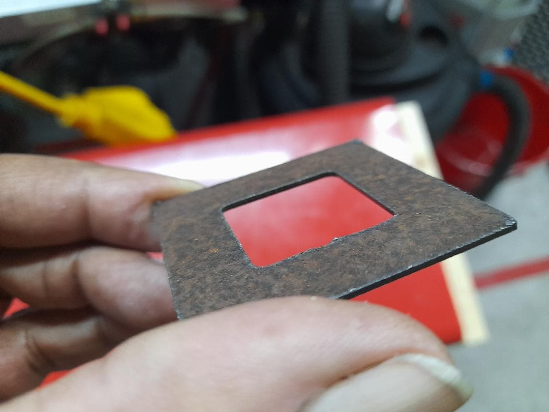
Have you run any kerf tests by cutting a square and then measuring its overall width to determine how much kerf with your machine actually produces on that kind of material at whichever speed your running?
The thicker material and the slower you go the larger your kerf width becomes.
If you’re trying to make a cut for let’s say a half inch bolt you’ll likely have to cut the hole 5/8 or greater to fit the bolt through right off the table.
It is amazing how hard cutting with plasma can make the edge of a hole.
For sure , change your kerf width to quarter inch see what happens. It’s pretty likely you’ll end up with a smaller hole.
Or try kerf width of .001 I think you’ll find that it does cut a different diameter hole.
Ultimately what I would do is determine what your actual kerf with is. Apply that to your kerf width settings of your tool in fusion 360.
And then make the hole bigger in your drawing in fusion 360 to allow for clearance.
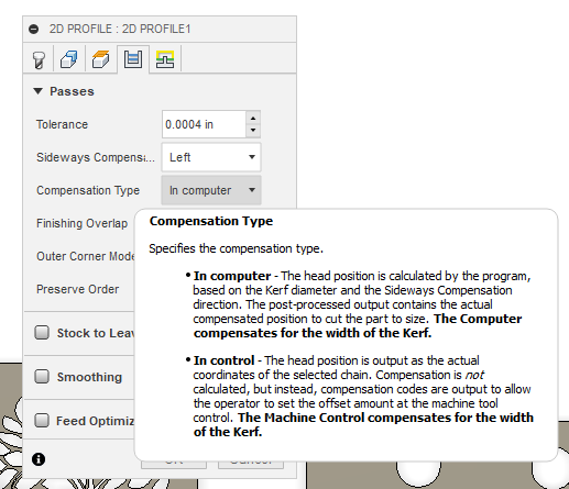
You need to increase the hole size by around .050", so decreasing the kerf by .010 is not going to get the result you want. Decreasing the kerf by .010 will theoretically give you a .020" larger hole. If you want a .500" hole that you don’t have to drill after cutting, you should factor in some taper to your design and program a slightly larger hole.
It’s worth it to test how wide the kerf actually is with the torch and nozzle that you have. I’ve found that mine works best with a kerf width of .040" on a .9mm nozzle.
Get some Step Drills. I probably made 5000 1/2in bolt holes on 2 Step drills. I probably could cut the holes bigger but I think a drilled looking hole with a little chamfer makes for a better looking product. on exhaust flanges i would just oversize the hole in fusion.
Did my usual machine maintenance this morning and did some tweaking. For 16g steel 30A, I set my kerf at .025" and at 150ipm The cuts are dead-nuts on dimensionally and there is zero dross.