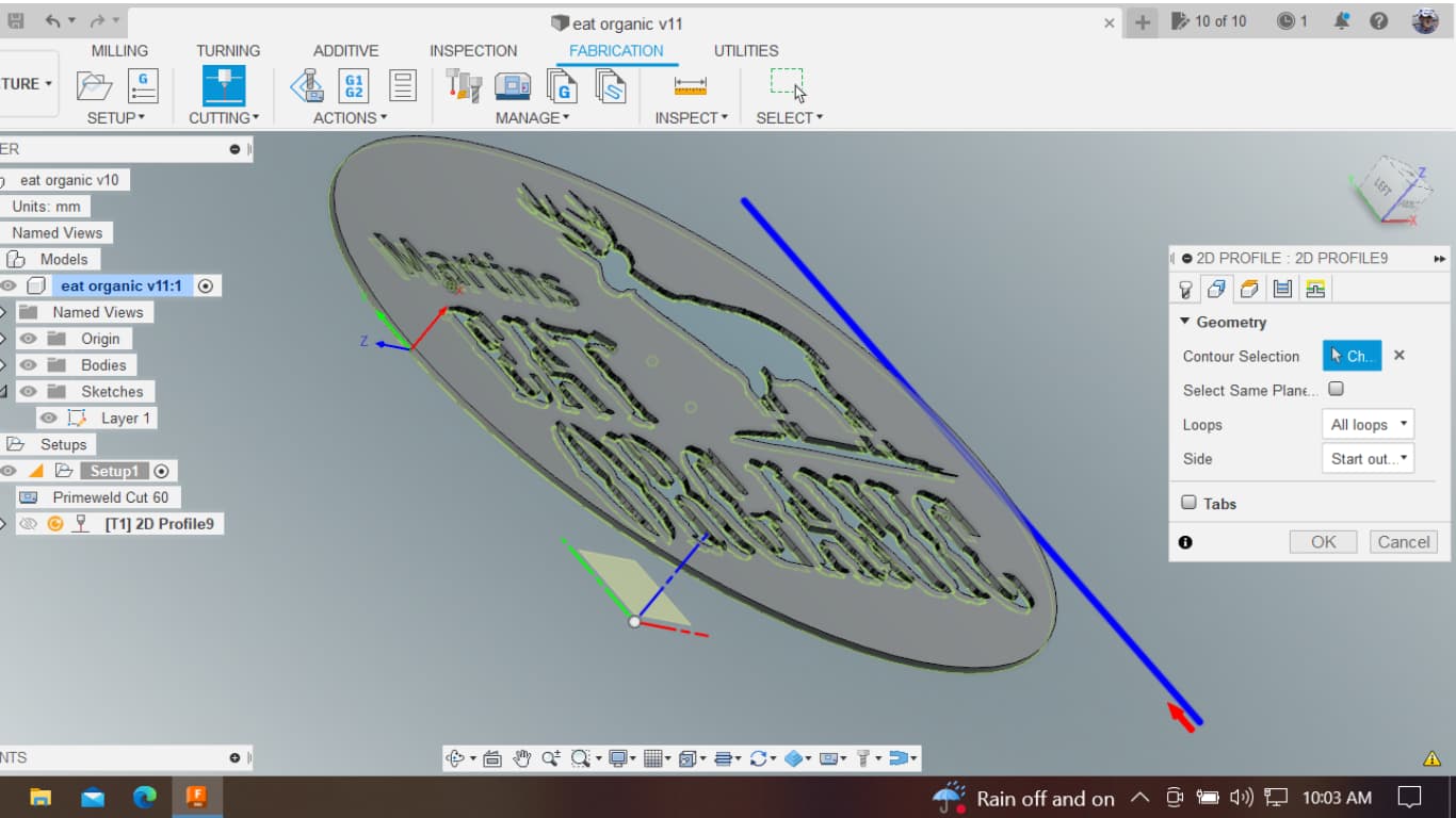
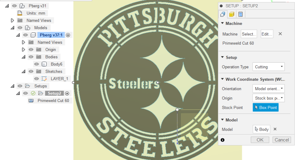
I have an issue I can’t seem to correct. When I go to Manufacture and Select Contour, the cutting direction is not in the same plane as my sketch.
My sketch plane is X-Y, but the Contour arrow is showing as a vertical bar and an arrow pointing in the wrong plane.
I am only using the free version of F360. Checked some plane re-assignment vids on YT and saw a sketch plane re-assignment option used. Maybe free version lacks this feature.
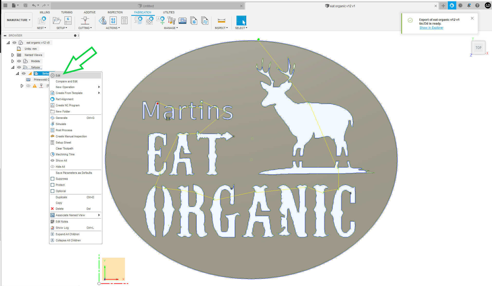
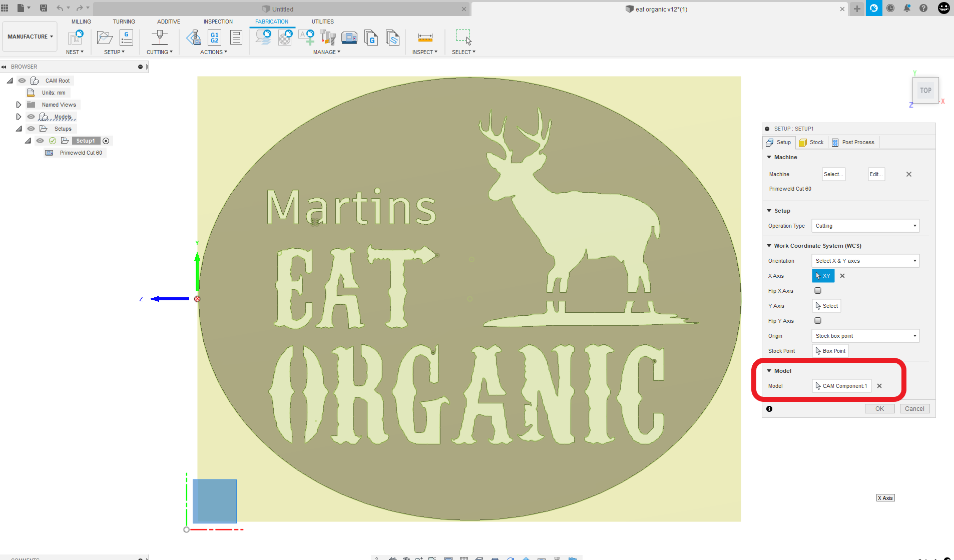
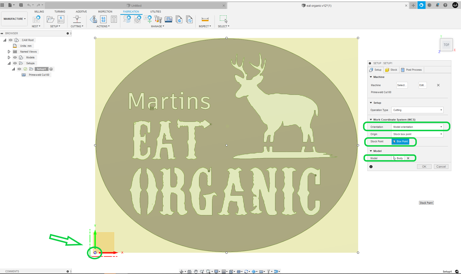
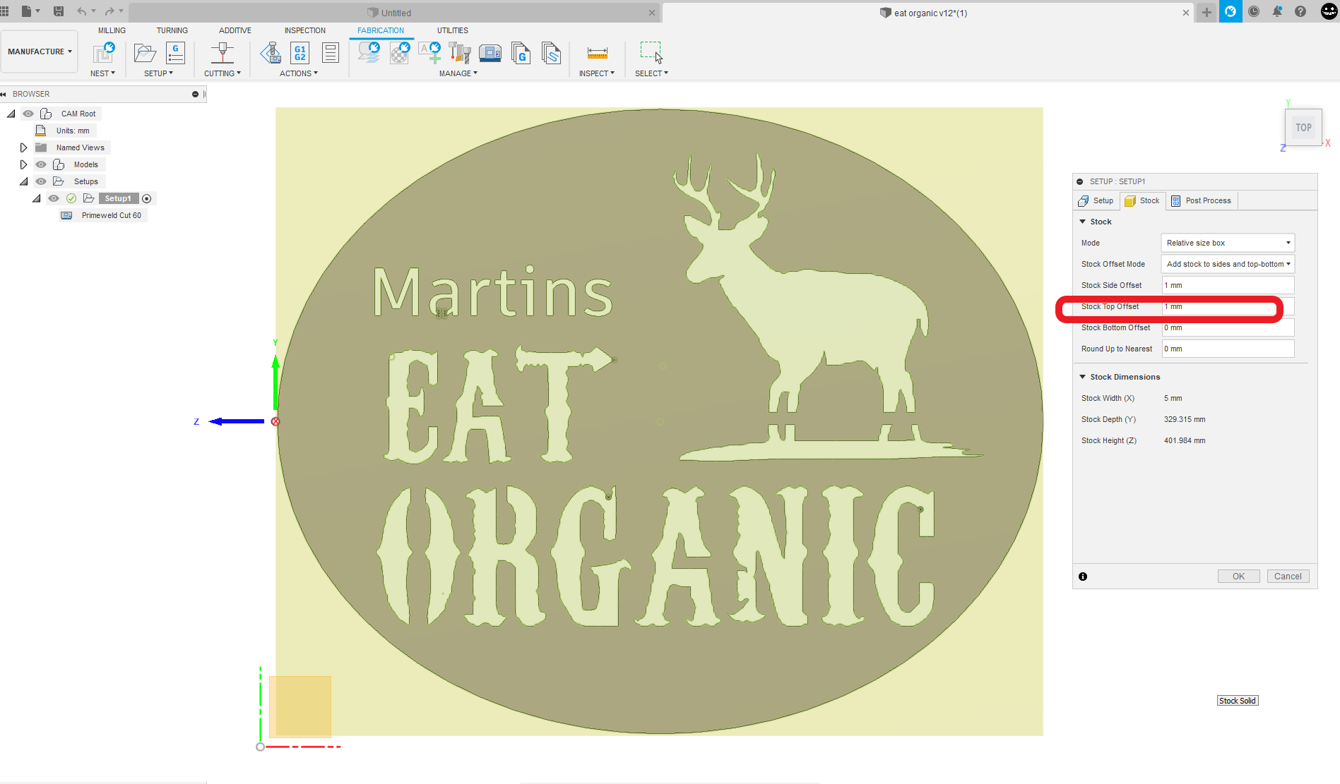
In your setup make sure that body is selected. And we don’t care about design origin we care about stock box point which ends up being origin in fire control. Both these settings are in the setup menu in the manufacturing space. When I get back to your computer I can also screenshot something.
Also you don’t have any single line elements to your design so I would turn off the sketch visibility so that’s not getting in the way of your selection process.
Wow. Thanks. I’ll definitely try it out, hopefully later today.
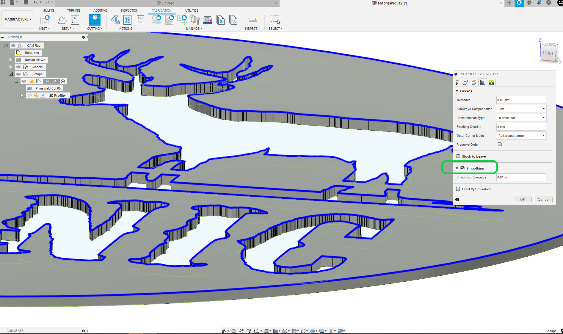
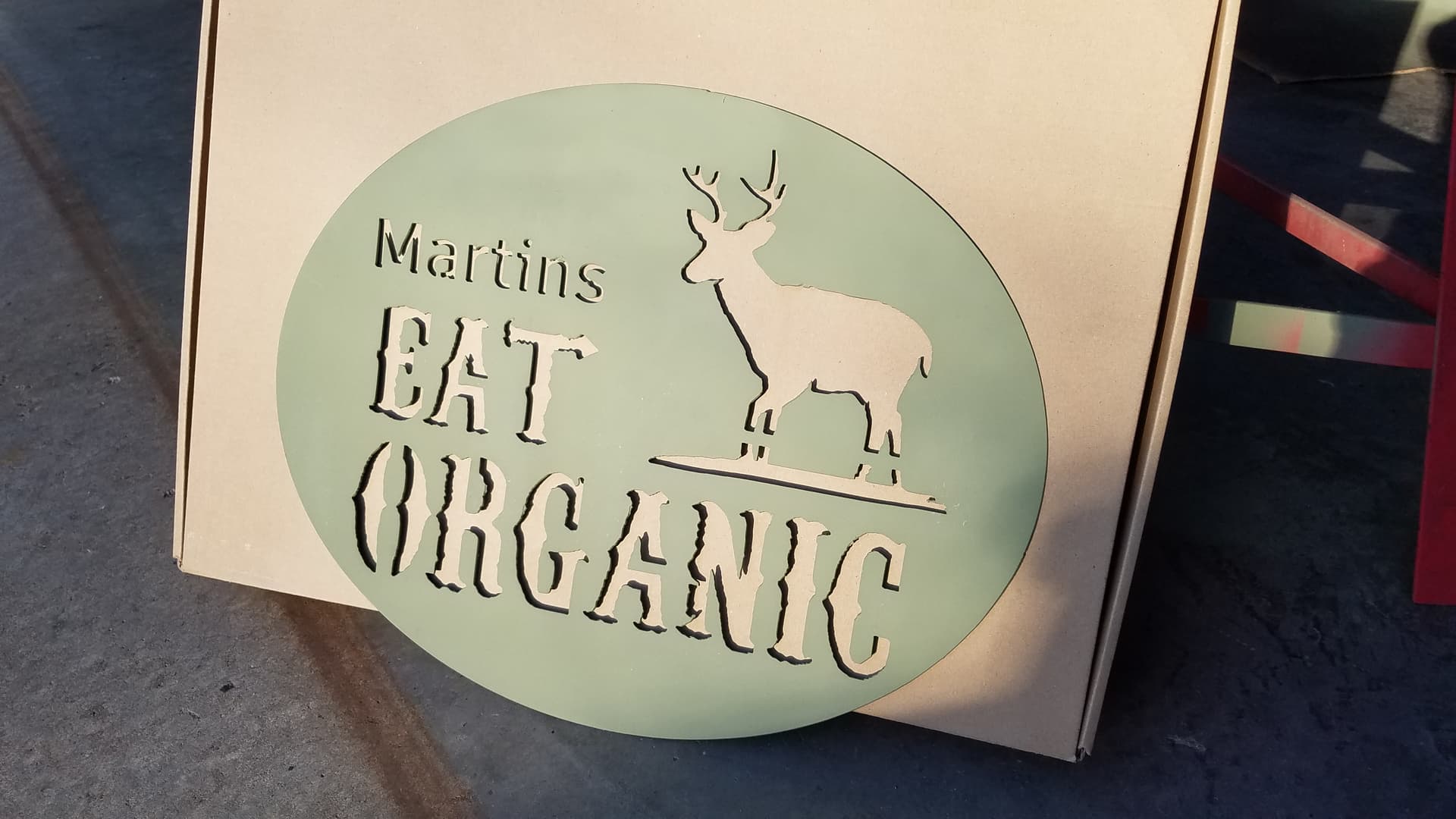
The svg file came from a member’s file share here. I had already smoothed a lot of the original lettering and replaced the outer perimeter with one ellipse. It had been drawn with hundreds of 1-3mm line segments. I believe he was going for a jagged appearance, but the lines were so short, I think it was just going to bloat the GCode and appear basically smooth anyway.
I may go through the steps you did just so I will more likely remember how to repair this kind of problem.
The sign is for a friend (obviously deer hunter) that I owe a favor. He said his wife is constantly buying metal signs off internet.
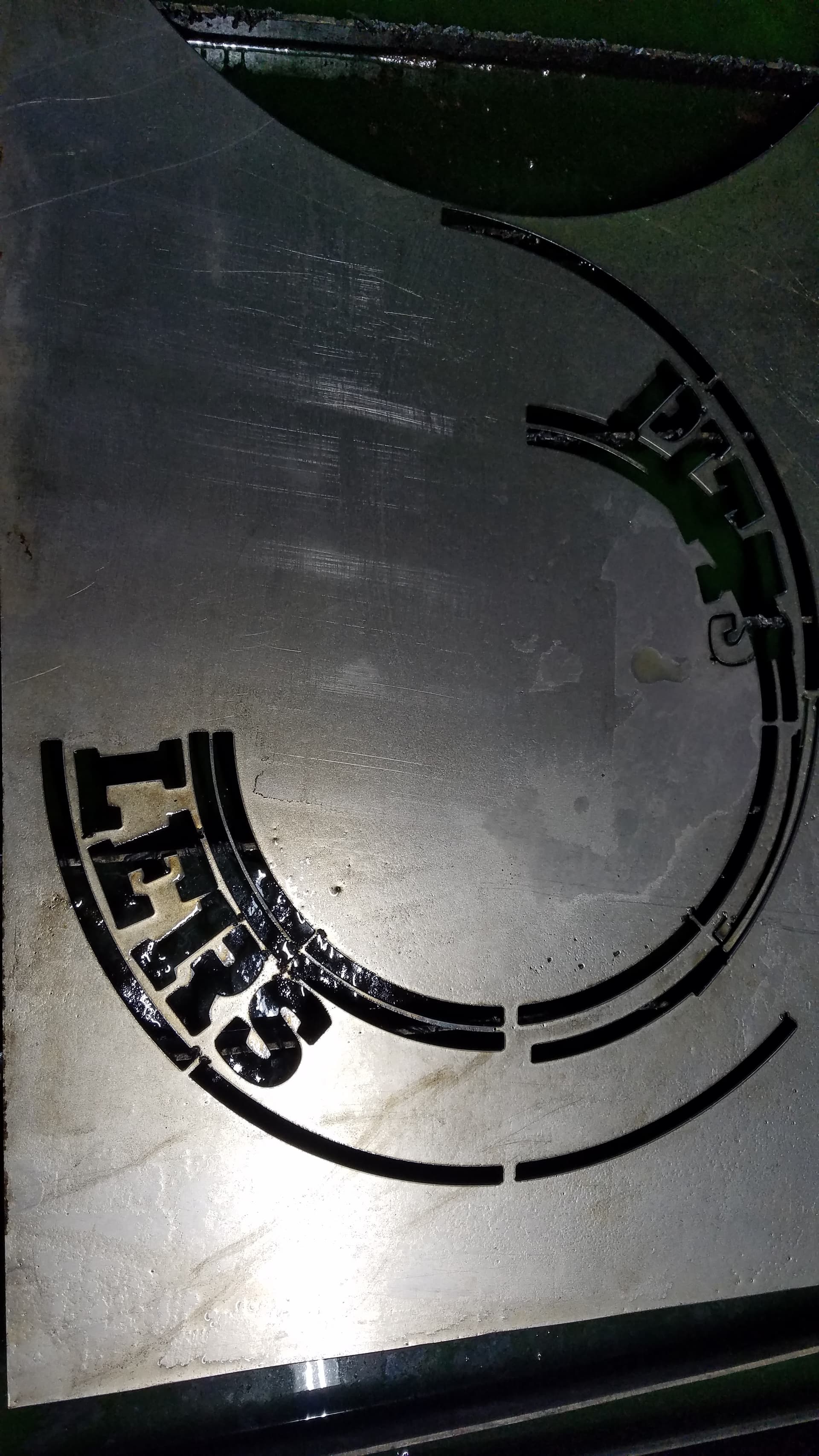
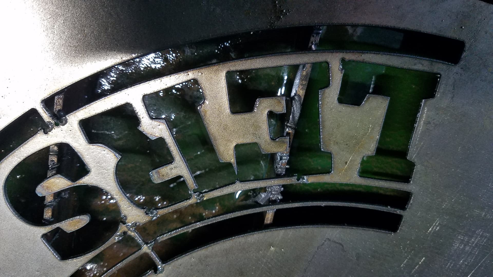
Awesome results. I cut this out and it turned out great.
After that, I changed the name for another friend, and it was not so good. But, I think it was my electrode was worn out. I will try another run in the next few days.
Looks really good though. I will be giving it to him tomorrow at work. I think he will be very pleased.
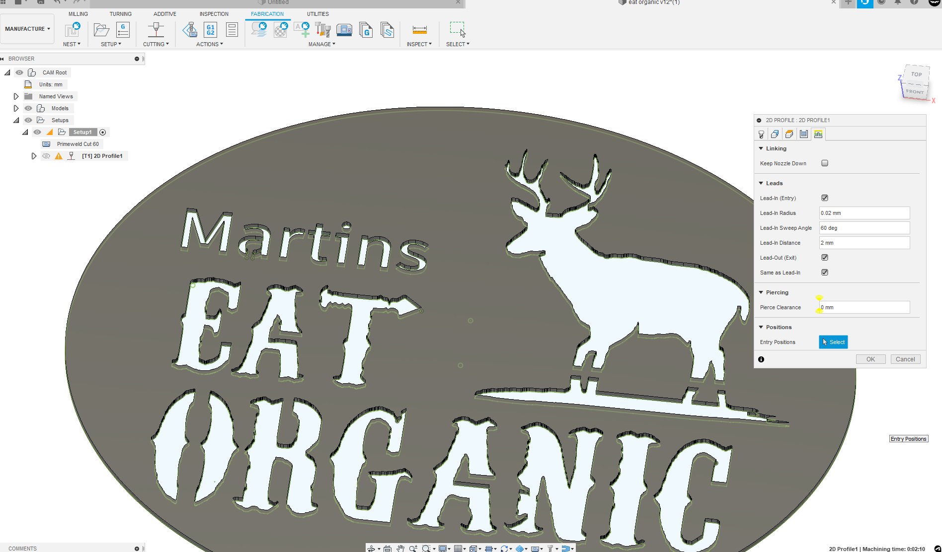
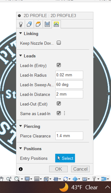
The changes to the lead-in/lead-out definitely helped. I will be more careful with that in the future.
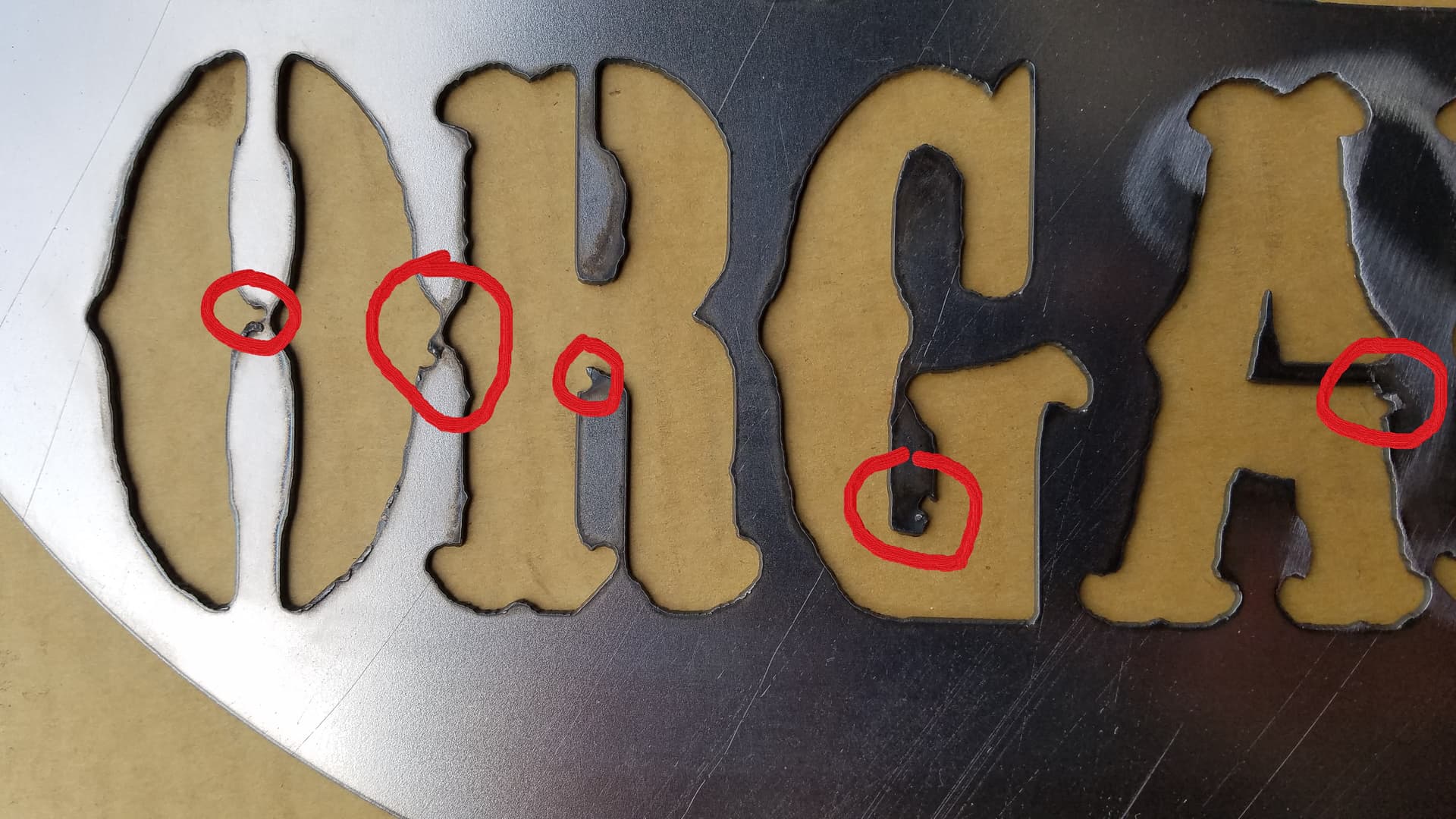
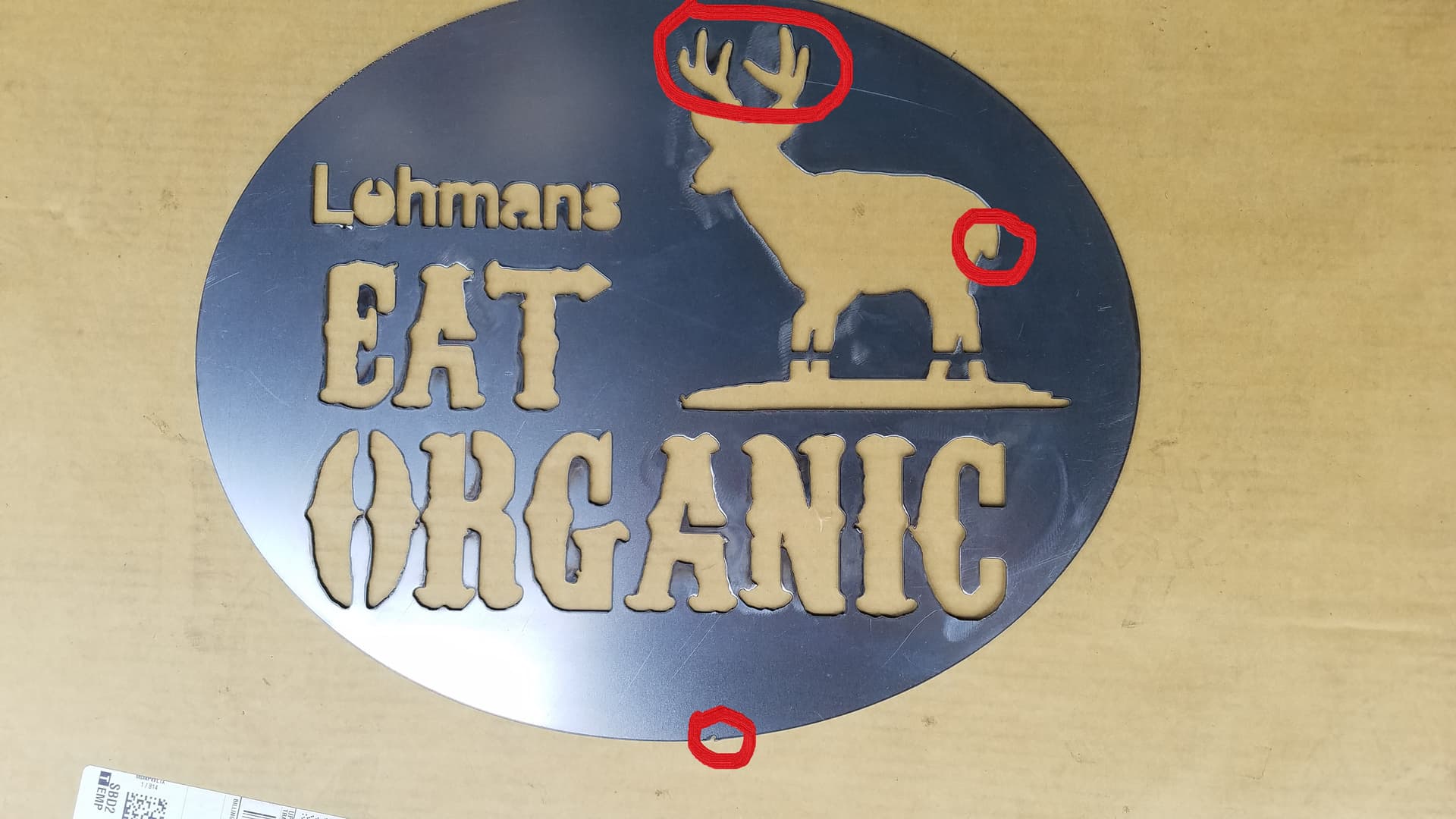
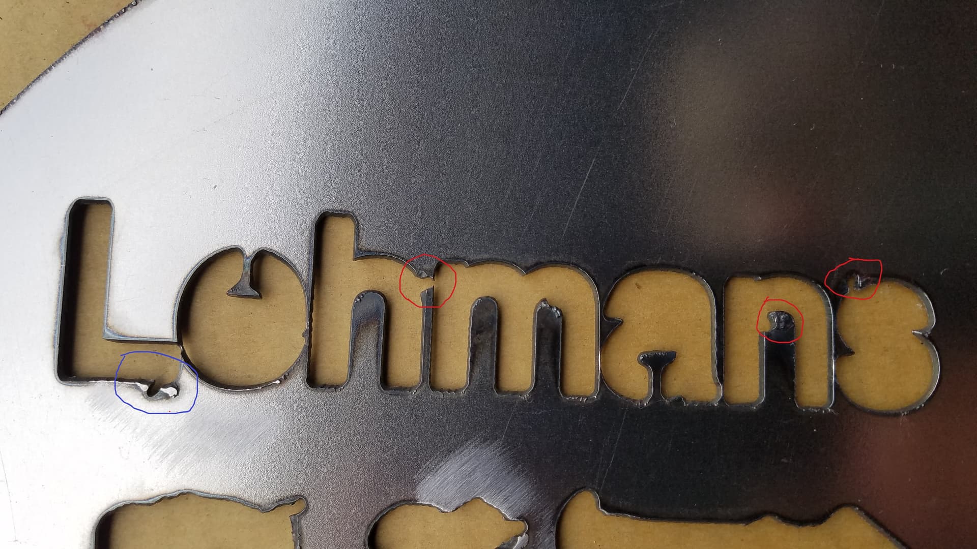
I made the same changes to my new version that you had made to my original (smoothing, lead-in/out changes, lead-in radius). It creates complete toolpath, and even cuts the full pattern. But, the results are more crude than the original. Everything looks a bit larger, the edges to both changed and unchanged text is much less crisp, features on deer are oversized and less definition, and there were several bad lead-in/out cuts.
I wasa especially impressed with the “i” in the word “Martin”. Never seen it cut a circle so small and clean. That is amazing and showed me the potential of my cutter if I reach it’s level of performance!
Any idea why I would seem to get different results from what I thought were the same settings?
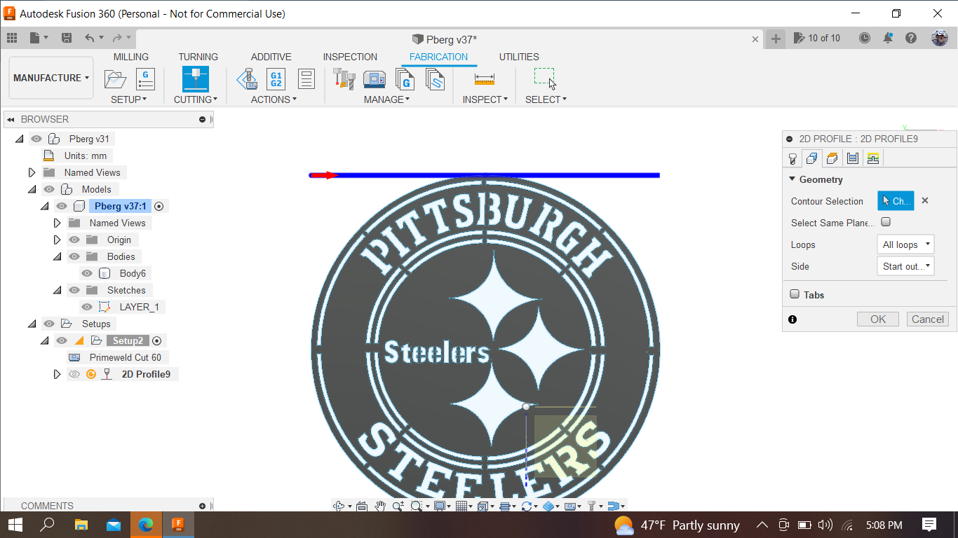
I am having the same cut direction problem with another file. Again, it’s one I pulled form Fileshare and reworked. This one, literally everything except a few of the letters needed to be redone. When I start from scratch and select my own sketch plane, I have no issues.
When I select the cuts, the direction is again improperly oriented. I have the settings in the “Setup” the same as you showed me last time regarding Orientation and Model:
Just watched the video. Thank you so much from “West Sider 1”!
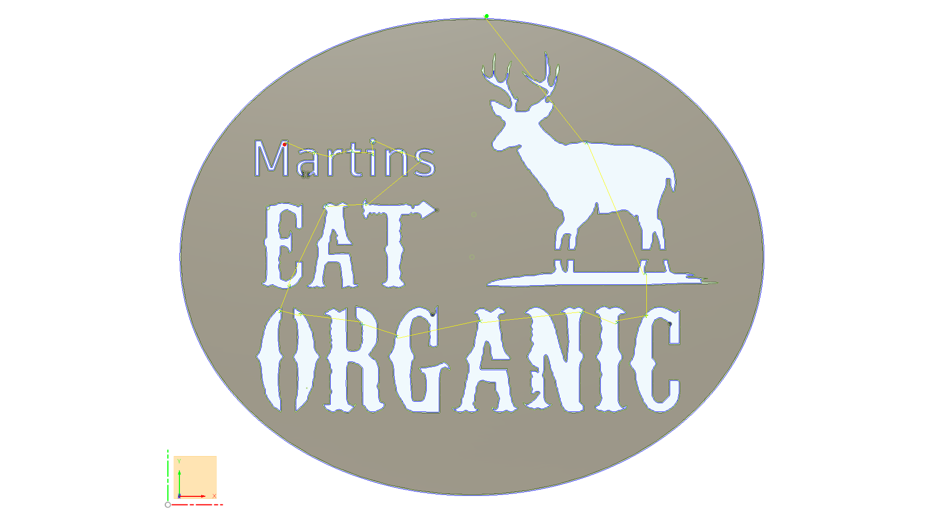
When trying on my own, I saw how those arrows along the sketch planes were segmented, but I didn’t click on them like you did to re-orient. Doh! I was soooo close.
Haha, you’re Canadian and don’t use metric, and I am Southern Indiana redneck (work for Toyota), and have worked for Toyota so long I have a hard time thinking about Imperial measurements except in 1/4" or greater increments. All the threads talking about cutting in IPM keep throwing me off.
I will try the re-orient on my own, adjust those “e” dimensions, get a successful cut, then report back and post a new version on Fileshare.
Thanks again. I definitely learned the lesson on the video. Keep’em coming!
BTW, I also watch Tyler Beck F360 videos on Youtube. He has some great tips.
It’s crazy I know. I’m in rural Canada and live the stones throw away from the US so the only time I really use the metric system was in school or doing Celsius to Fahrenheit conversions these days.
Toyota is the best stuff going. I have a lot of old Toyota’s. I am a huge fan.
I will check it out, I’m still a student of fusion 360 after all and have a lot to learn.
Check out this drawing I did as an example . 80 Toyota 4x4. I wish I had one in this nice shape but I’m lucky to have a few of them. I have several mid-70s pickup trucks as well.
And my buddy has a Toyota wolverine which is kind of the first pick up 4x4 on a '70s chassis.
Nice! 25 yr employee, working on new model designs. Not Fusion 360 though, haha.
I have two 1995 Toyota Tacomas, both of which I resurrected. One was in a salvage yard and I bought it for $1400, put $1000 in parts, and it the best running/driving truck you could imagine. The other, the entire back half of the frame was rusted off. I built a new frame and put on a flatbed and overhead rack. Wrong PC or I’d post pics.