Just sharing my experience with the shimming of the Z axis.
My shims calculator ( the newest revised version) suggested to put 2 upper carriage shims per side.
After I milled the base plate with 1/2 “ bit, I could see ridges of about 1/1000 “. I checked the perpendicularity of the spindle and it was way off. About 10/1000 “ when measuring over the 3” travel. The spindle was tilted forward, therefore the shims that were calculated were making this worse.
I removed the shims and I had to put shims in the lower carriege of about 0.25 mm ( 10/1000 “). Basically I used the Y axis shims to get this done.
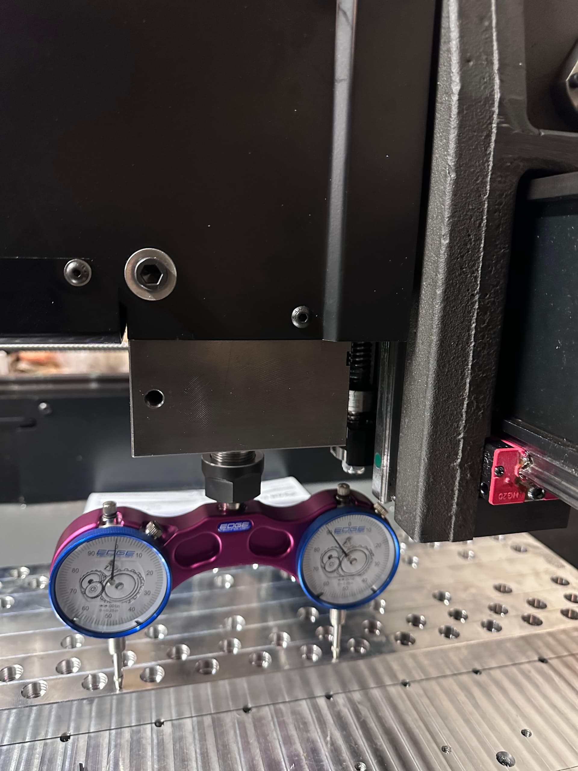
What I did is to remove the spindle and tram the z axis first. It turned out to be almost perfect across 6 inch travel of a 246 block. Less that 2/10000 “.
After this I mounted the spindle and I had to shim that too to correct tilt and nod.
Now my nod is less then 1/1000” and the tilt is 1/10000”.
It took a bit of work and I used a tram tool to get things better.
I will make another pass to the baseplate to check the results tomorrow.
Cheers
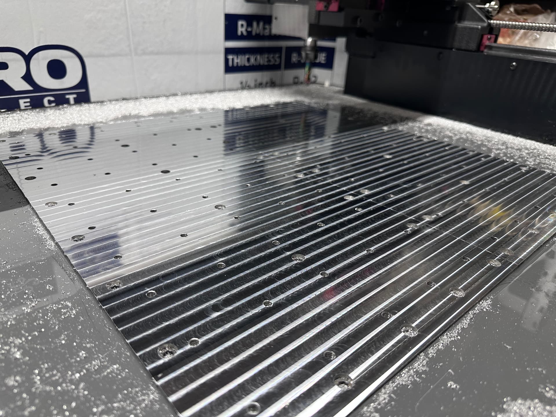
I did a dry surface cut of the baseplate after the tramming of the z axis and spindle. Now I can barely feel any ridges. I can call this a success finally.
The 1/2” mill did quite a good job at getting a shiny surface even though I can see tiny scratches on the surface probably due to the dry cut.
My experience was similar - the calculator told me two shims on the top guides but that just made it worse, I ended up with three shims on the lower guides and its almost dialed in perfect. The good thing is its an easy thing to measure.
Mine said 0 shims on the calculator. After I surfaced the base plate and did the final Z axis, it took all of the provided bottom shims to get it to less than .0005 over 3”. It was .0035 with no shims. I think that is within the range they mentioned for assembly.
First thing I removed the spindle and corrected the tilt and nod of the Z carriage with the usual shimming up/down carriage as described by Langmuir videos.
One extra thing I did was to shim also the top of the left upper carriage to correct a minor tilt of that too. This was almost perfect at the end. I noticed that on a 2-4-6 block my nod was perfect top and bottom of. 6 “ travel but a bit bowed in the center with an error of about 20 microns. Maybe due to casting or not perfectly flat linear rails.
Then I assembled the spindle and rechecked and it was off in tilt and nod. I corrected the tilt by placing shims in the upper left edge of the spindle block and also same shimming in the lower right edge and I secured this tilt with the right and left bolt before tightening the back bolts. In this way you insure the tilt correction is maintained when you remove the side bolt to assemble the spindle cover.
For the nod in my case, I had to place two 0.03mm shims in the back top edge of the spindle block before securing the back bolt.
Hope this is clear. If not I will try to post some pictures.
I found that once the spindle is mounted, you can add/subtract shims without removing the spindle. Loosen all the bolts first so there is slop, If you need to shim the top (to add nod) then undo the 8 bolts and slide the linear bearing out, place the shims on the front of the bearing and slide it back in, using grease to hold them. If you pull on the spindle towards you, you should be able to slide the bearing back in place without the shims touching the spindle carriage, then center the bolt holes (using a tapered punch) and put the bolts back in.
If you are doing the bottom shims, remove the three bolts and lift on the carriage towards you to swing the carriage up a tiny bit - I used a large screwdriver against the X gantry to separate the carriage enough to slip in shims - again center using a center punch and put the three bolts back in. Note the bottom shims have an orientation with the hole, the hole is towards the bottom and I think the larger space to the side of the bolt hold is to the outside. Look at where the bolt is place compared to the mating surface and it should make sense.
I agree with you Mike 100%, but I thought that is important to correct tilt and nod of the Z axis carriage first to insure perfect perpendicularity during the movements first, and the mount the spindle and correct again tilt and nod of the spindle only. In this way we insure all is consistent.
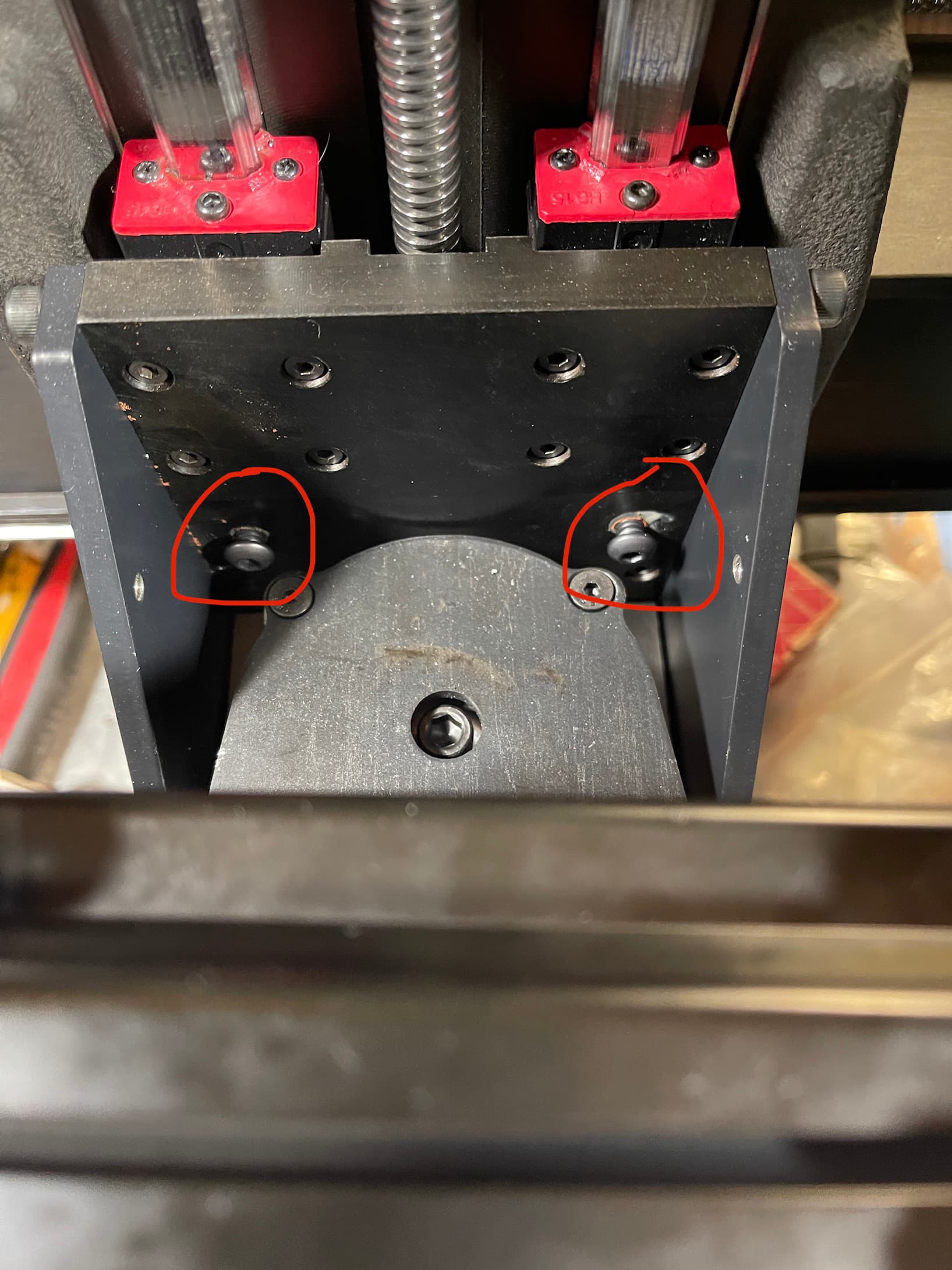
oh yeah that part not bad at all, I was just curious exactly where the shims were being placed to shim the spindle outside of the z caridge. Also curious what these bolts are for. Saw another guy correct tilt with some threaded holes on the sides.
These bolts you need to remove and use them to secure the spindle when you move it in the upper position. In that position you will secure the spindle with these bolts and with the lower bolts you previously used to secure it.
@DanLev I had the same problem, and my machine was shipped in December. I ended up needing two shims down low after I did my own measurements. I agree with @Speppino’s advice.
Im thinking I’m in the same boat. Calc (current version/new) says to add 2 shims to the lower which did. My base plate is all over the place so all I did was clean up a smalll area to make “flat” than checked nod and tilt and its all over the place. .015" on nod and almost .030" on tilt. that’s on a granite square