I’ve given up on fusion360, trying sheetcam, seems much easier.
However, still cant get a cut to work.
I run crossfire break in.tap, works fine, table moves back and forth.
Go to sheetcam, load bottle opener keychain v2.dxf, drawing appears in sheetcam just fine.
Run post processor, and code looks like this:
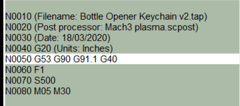
I run the job status report, looks like this:
Did you define a toolpath? That would go between opening the drawing and running the post processor.
If that’s all the code that you got out, it would seem you haven’t defined a toolpath for it to create any code for.
Thanks jamesdhatch, I figured it was too easy. I’ll go read about toolpath.
any tips ?
you’ll have to define a tool (I have them defined for each type of material so most of the settings are prefilled for me).
Then you create a new jet cutting operation (first icon in the operations menu on the left).
You’ll pick the type of offset (inside, outside or no offset) and which layer (I use different colors in my design so I can define the cuts by color since Sheetcam assumes each color is a different layer. I’ll use black for instance for the outside offset cuts and red for the inside offset ones. As you use Sheetcam you’ll find you can create more layers for grouping different cuts with different lead-ins, lead-outs, etc to get finer control.
Then you run the post-processor.
@jamesdhatch. THANK YOU SIR!!!
I got my FIRST cut!!! WooHoo!!!
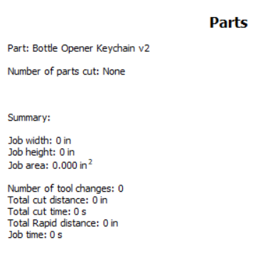
I taped a sharpe on, looked like I was ready to cut,
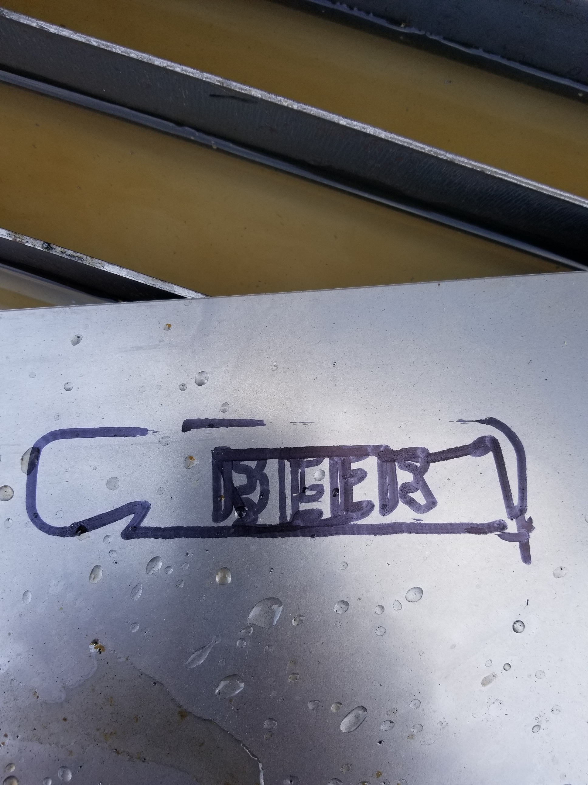
Fired everything up, and my first cut! It aint purty, but it is a cut! Now to learn how to refine everything.
2 Likes
Arclight dynamics has a series on SheetCAM on you tube. Well worth the time to watch.
3 Likes
yeh, ive been watching youtube for 2 months now, my eyes are crossing.
Now that I have a cut, I’ll go back and watch again, maybe make more sense now.
Sometimes that’s all that it takes to “click” and then what you watch & read are suddenly understandable. A lot of us forget that there are a lot of concepts involved that aren’t really common in most people’s life experiences. It can be like trying to learn practical applications if calculus ![]()
Congrats on your first cut bud, nice to see your making progress.
If you want to post the metal thickness, your cut speed and what tip your using I am sure we can figure out why your blowing those letters out.
It is a good start!
I suspect that it has to do with the inside and outside cuts being reversed.
1 Like
Thanks for the help guys (and encouragement). I was really getting frustrated, now I’m excited!
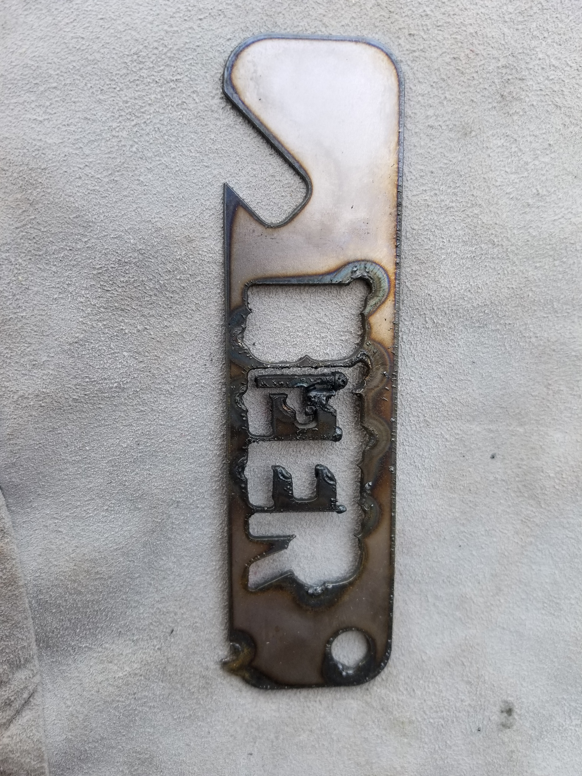
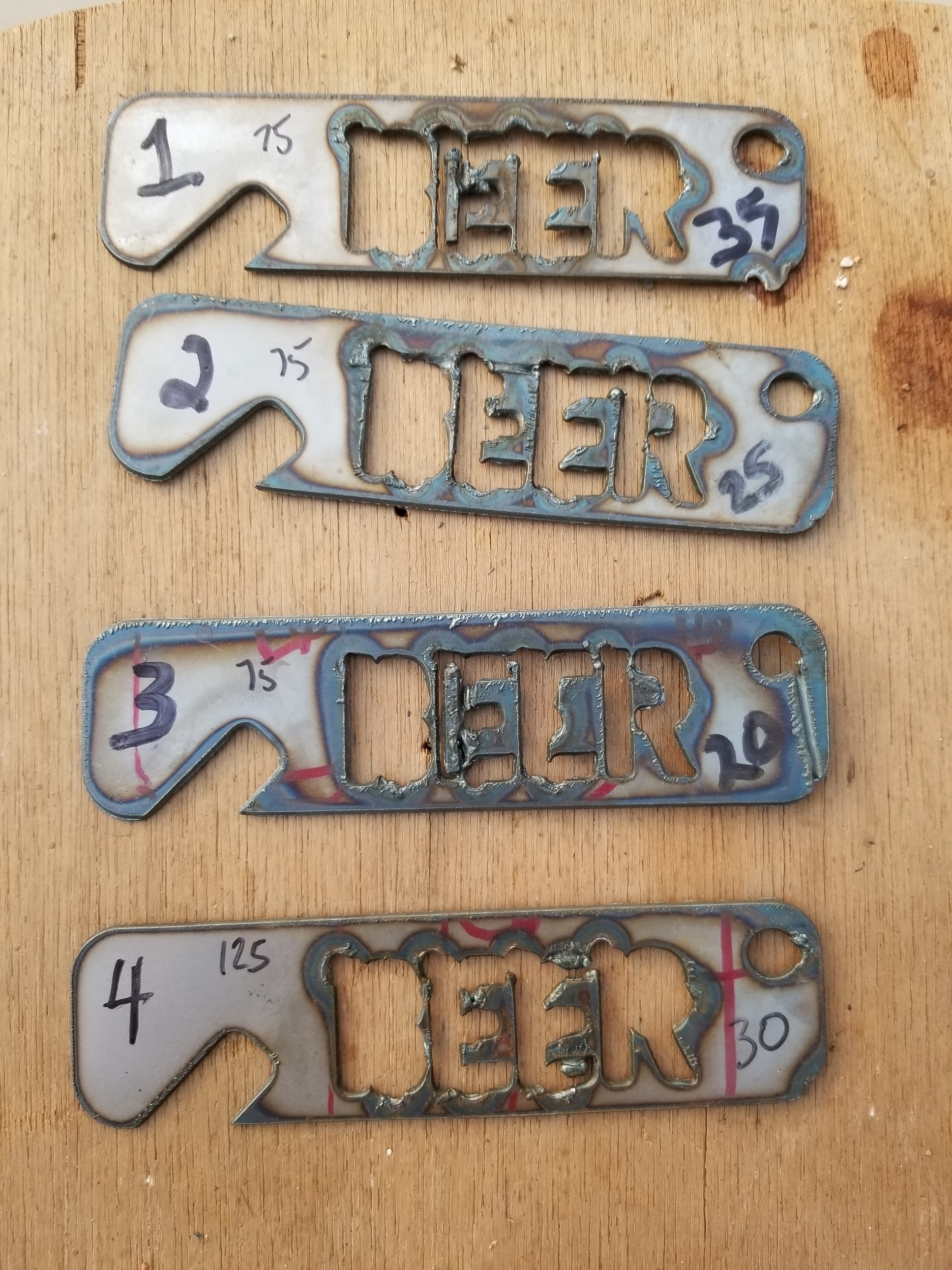
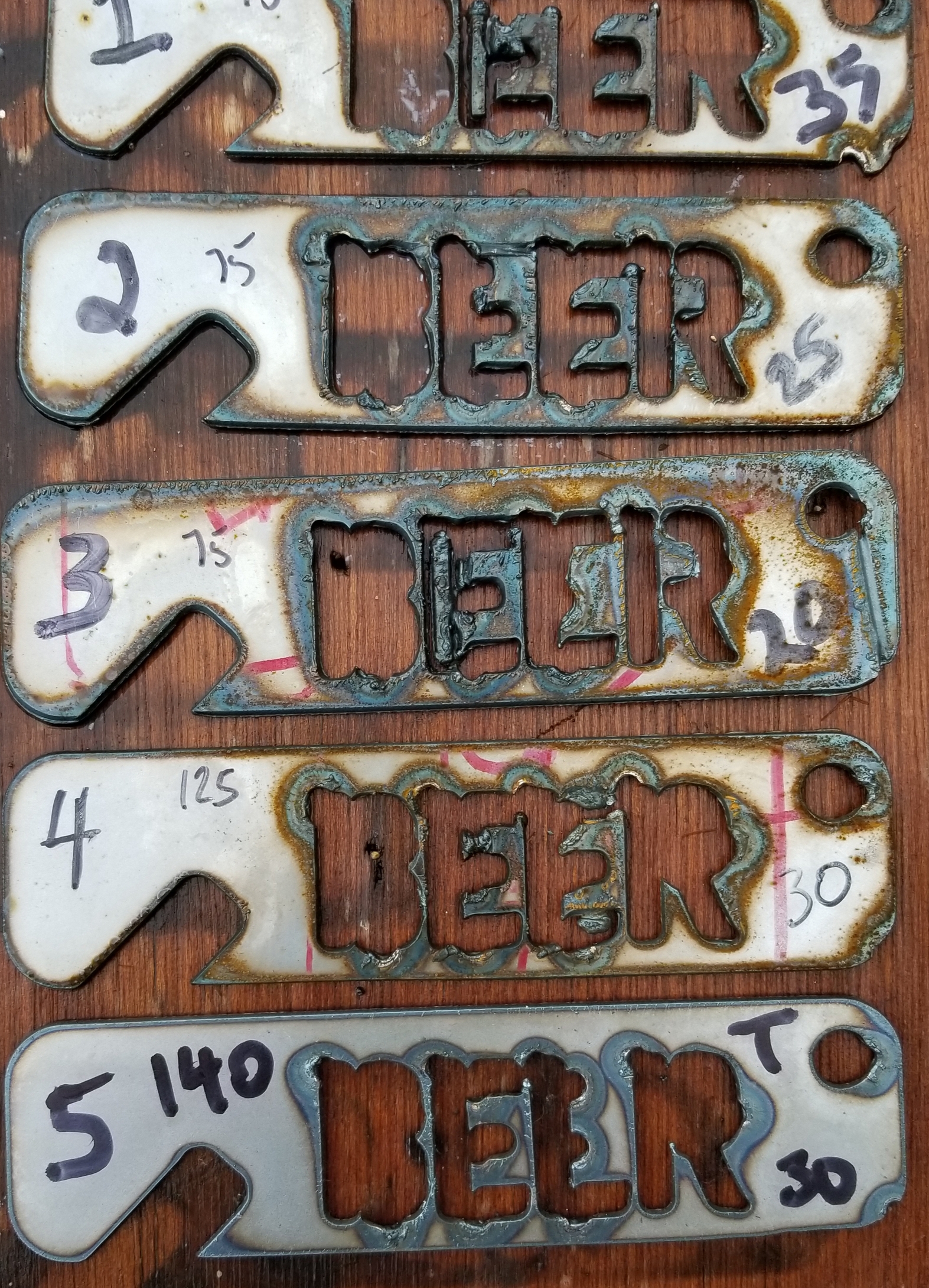
Here are my 4 attempts today, 1-4 sequence, first 3 at speed of 75, last at 125. Tried 35, 20,25,30 amps
Tip is what came with the rw45, how can I tell the size?
Material is .063
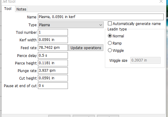
Here is the tool definition.
If you post the DXF (or SVG) file, I can path it in Sheetcam and take some screenshots for you.
I believe the tips I got with the RW were .8mm. I bought 1mm and .6mm ones for use at different power levels.
The .dxf was downloaded from fileshare, no changes. It looked like the simplest one with letters.
I planned to design my own later once I saw how things worked.
So I think the problem is in my setup, did not know about tip sizes until now.
Post a screen cap of your Operation dialog. I believe that is where your remaining problem is.
Edit: Add a screen cap of your SheetCam view after you’ve imported the drawing. This will show how SheetCam ‘views’ the data.
Ya, it is a learning curve, taking it all in takes time and practice.
If you have a large tip in with 16 ga material your going to burn a very wide kerf. If you want to run another test without changing your tip (baby steps) push your speed up to 150 or 180 ipm and see what you get.
Basically your burning thin material with a tip made to burn thick material. Another thing you could try for fun is use the same tip and set up and try to burn a piece of 1/4" thick scrap and see what you get. But remember the bigger the tip, the thicker the steel means less detail.
Your doing well, just have fun with it.
1 Like
Thanks for the help, still trying…
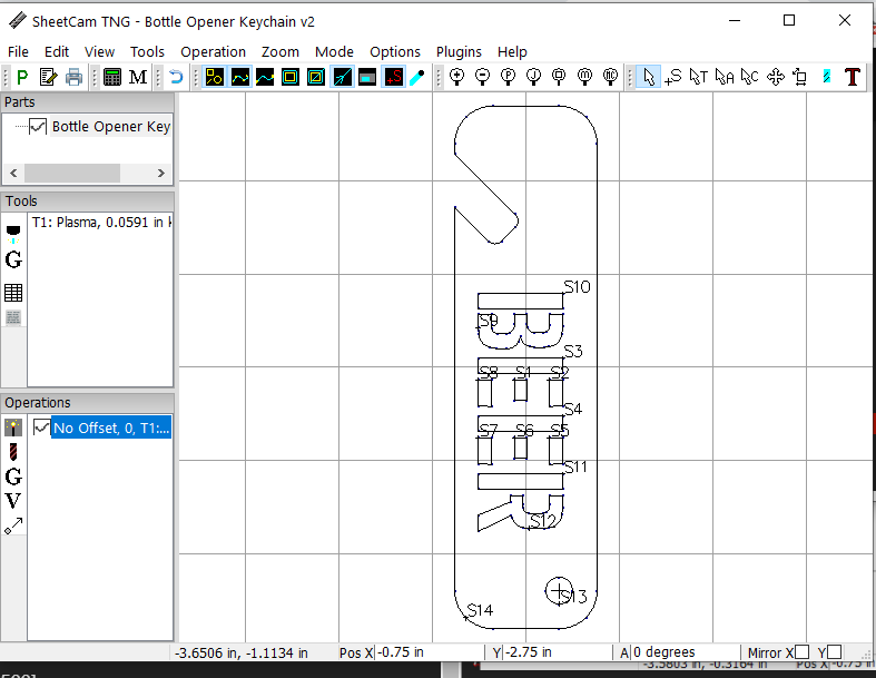
Loading new .dxf (from file share, no changes)
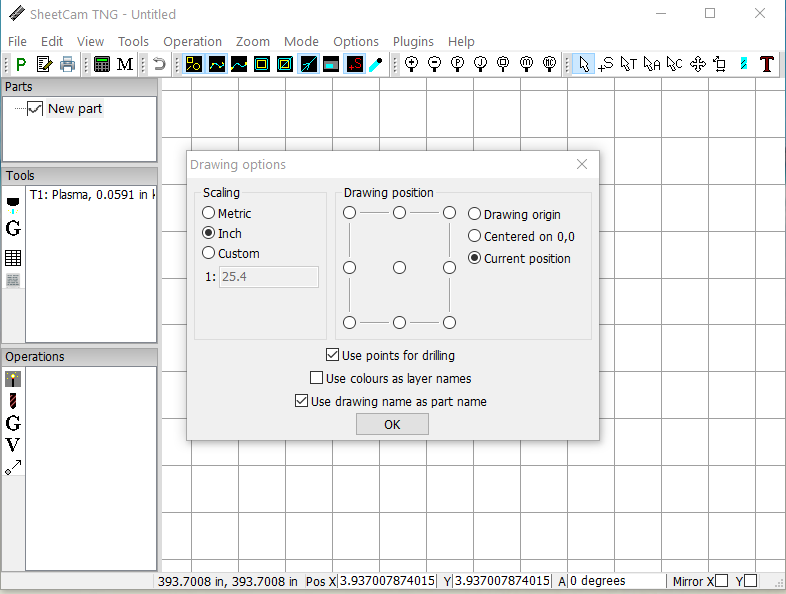
scketch loaded

adding operation
post processing completed
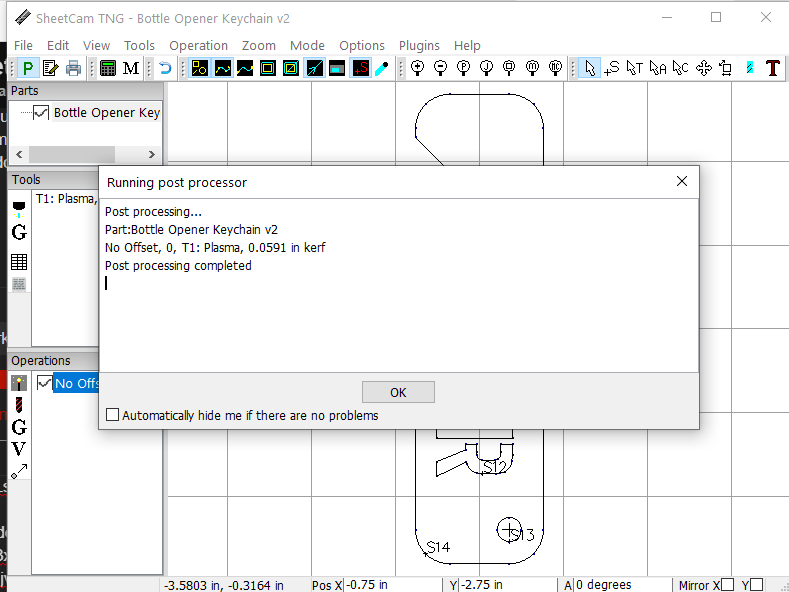
sheetcam done, going to mach 3
also changed tip this morning, tip on left(bigger) was on torch, tip on right (smaller) is one used on #5 try.
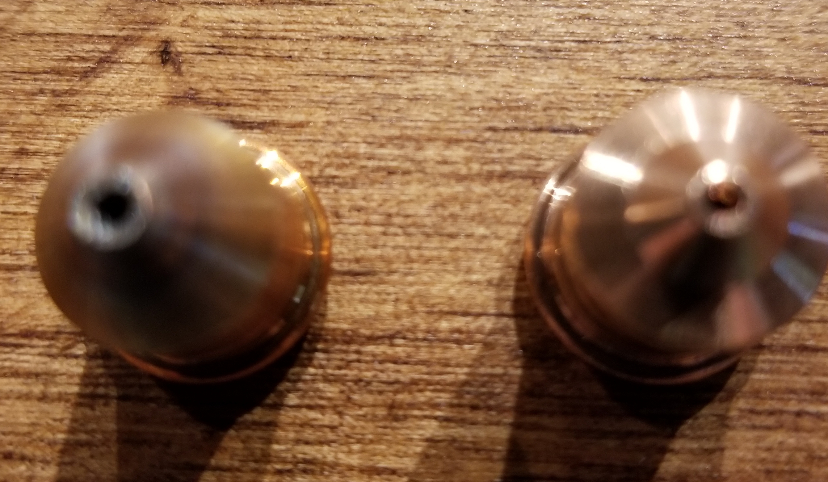
bumped up rate to 140.
I bought extra tips with origional shipment,
can not find anything on web about size.

try #5
and, I should mention, air is marginal, 4.7cfm at 90psi. From what Im reading, should be ok for this small part, plan to upgrade to 11cfm or better once I get going.
Okay, here goes.
I downloaded the DXF from Fireshare. In Sheetcam I selected New Job and then I did the Import Part to bring the DXF in. This is what Sheetcam looked like when I did that.
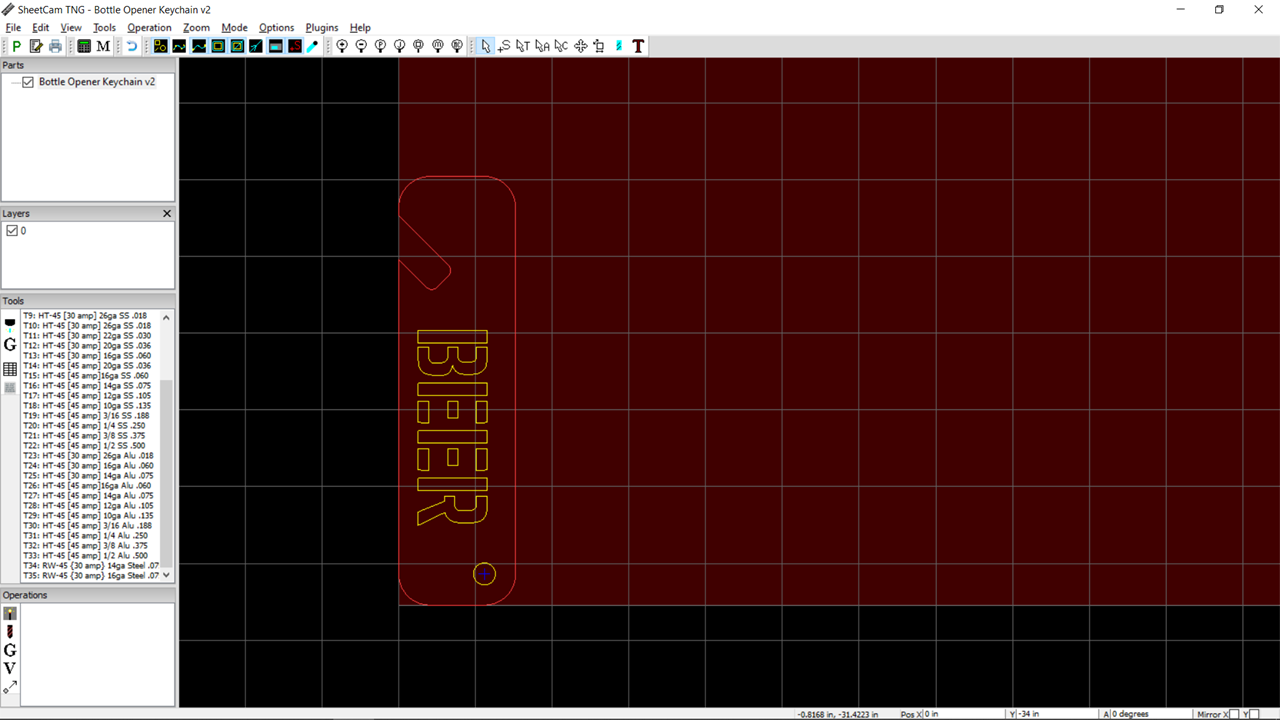
Notice over on the left side I have a “Layers” box under the Parts box. You’re going to want to show that. Click on the View menu option and then the Layer Tool. You’ll then see you have 1 layer (color 0). Sheetcam looks at the colors in a file and assigns them to different layers.
I’m going to assign the outer cut line, the letters and the hole to different layers. That way I can create different cut parameters to each cut. The outside I’ll want an outside offset so the waste material is outside of the cutline and that’s where the kerf & lead-in will be. The letters I’ll make an inside cut so the inside of the letters that will be the material that drops out will be the waste side. The hole will also be an inside cut so could also be part of the letters layer, but I find smaller objects might need more tweaking so I tend to put holes in their own layer - just personal preference.
For complex parts I might have a dozen layers with different lead-in/out values depending on the intricacies of the shape. But for now I’m looking at 3 for this one.
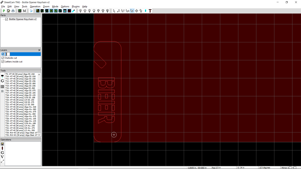
You define layers & the lines/cuts that go into the layer by clicking on the Contour tool on the menu bar (the upward facing arrow with the C behind it). Then go to a line and right-click. Click on the Move to Layer in the pop-up and then the New Layer and give it a name. I tend to use something descriptive so I know what part of the design I’m cutting - like “Outside Cut”. That name will show up in the Layer Tool on the right and will also be in the dropdown when you are defining the cutting action.

Do it again for the letters. You can right-click each letter or do a mouse click & drag over all of them to select them (that’s what I did and it’s why they’re colored white). Notice you can see the first layer I defined is now in the Layer Tool on the right (along with the original 0 layer)

And then the hole. But for this one I just renamed the 0 layer since that’s the only design object left on that layer. Just click once to select and then a second time to open the edit box next to it. Then just type in the name and click Enter. Yours should now look like this.
Now that we’ve got the parts separated into layers, we define the cuts. I should do them in the order I want them to cut but I don’t spend too much time thinking about the order right now and I’ll just rearrange them afterward. I like going from inside out and smaller feature to larger feature to minimize chances of bumping into a tip-up. I’ll also move starting points around on larger pieces where I want to avoid warping from concentrating too many cuts in too short a time too closely together. But for this one it’s going to be straightforward series of 3 cuts.
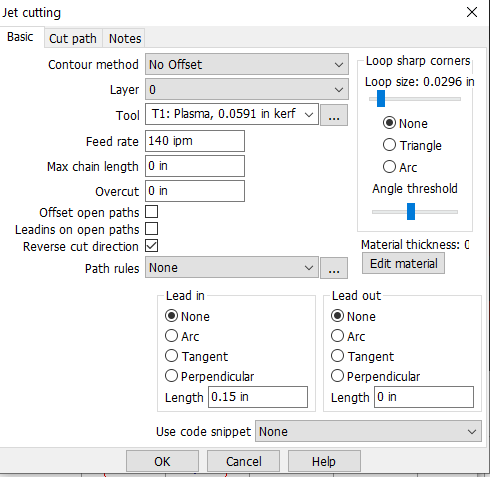
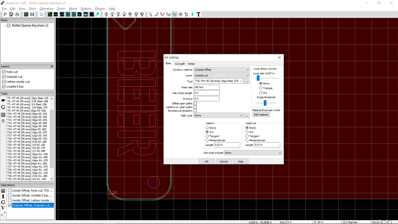
Click on the Jet cutting tool in the Operations box on the lower left. In the popup select the Contour Method (outside cut - places the kerf on the outside of the line), Layer (my “outside cut”), the Tool (I’ve got an RW45 std tip running at 30A for 16ga already defined and pick that) and I specify an Arc for the lead-in (too smooth the transition of the torch as it slides into the actual path) and a lead-in Length of 0.12in as I like to roughly double the kerf size to make sure I have room for the piercing point hole and then the travel to the line so there’s no kerf that touches or overruns the line I’m cutting. This is what it looks like.
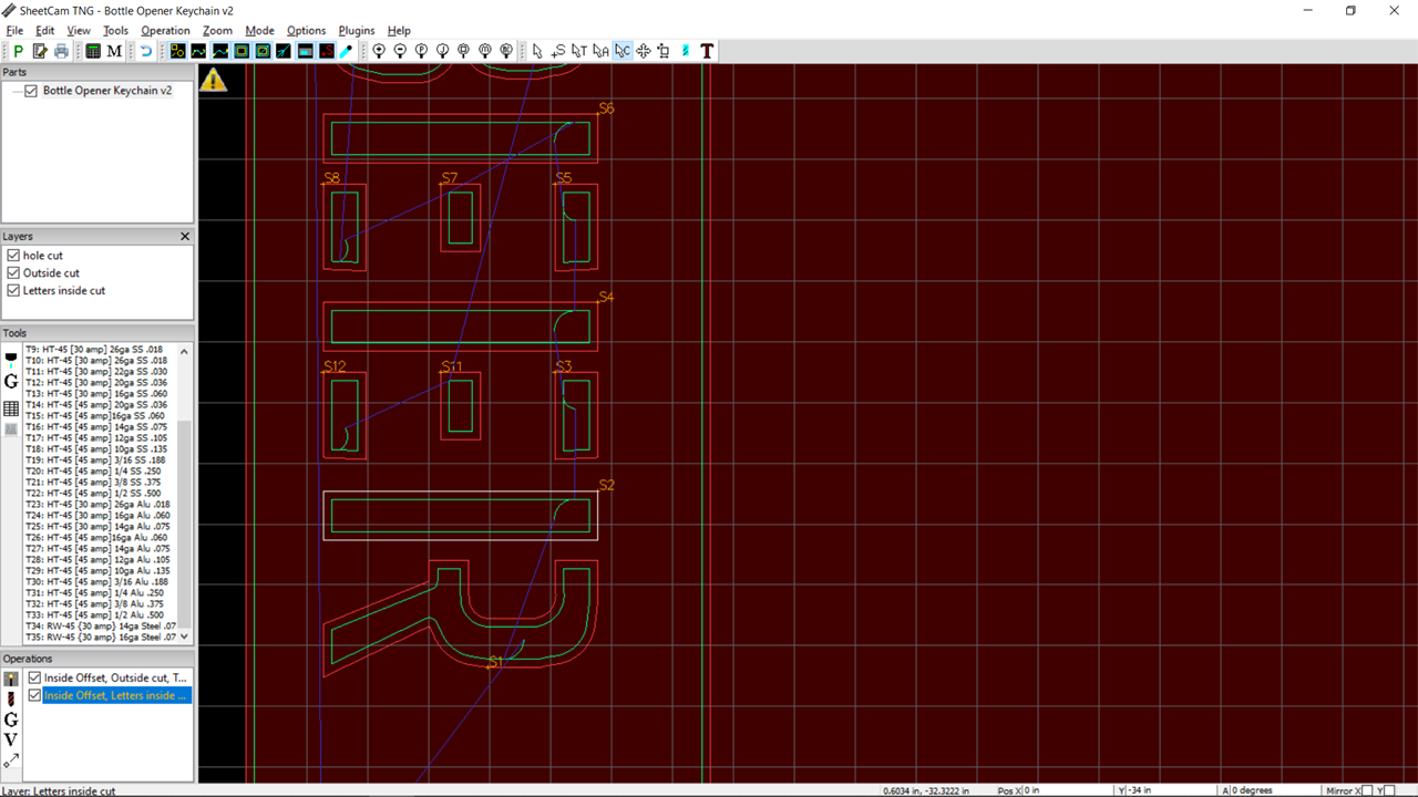
And then the Letters. Notice it’s got the Outside Cut one already over in the Operations box. I’m using the same parameters as the Outside Cut except I make Inside Offset the method I want so it treats the inside of the letters as the waste.

Here’s where my first issue comes up. Notice the Operation is highlighted Yellow and there’s the Yellow Warning Triangle at the top (and there was an error message that displayed - you can see it again by clicking the Triangle). It said the geometry prevented the settings from being applied to the selected objects and it wasn’t going to cut something.
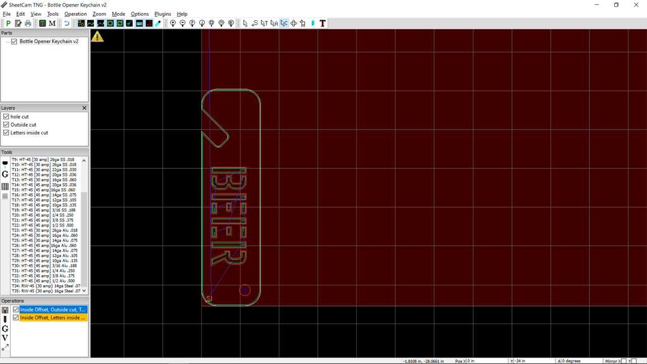
Usually that means my lead-in is too big to fit in all the bits of a design. I zoom in and see that the lead-in is missing from the smaller middle bars of the E.
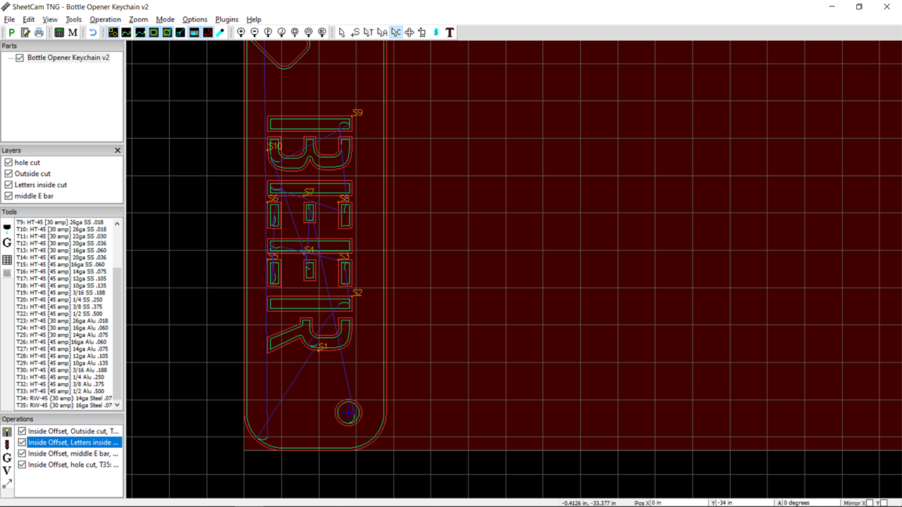
So what I first do is change the lead-in distance to see if I can fit it by shrinking my 0.12" setting to 0.1 or maybe 0.8" but that doesn’t work. So then I set the letter cutting operation back to 0.12" and move the two (remember there are two ![]() ) middle bars from the two Es to a new layer you can see I called “middle E bar”. That’s because I’m going to have to go smaller on the lead-in or possibly no lead-in at all and I don’t want that to apply to the whole set of letters. I ended up at 0.07" - I could have switched to a no offset (on the line cut) but then I’ll have the pierce point creating a divot on the line and I don’t want to do that if I don’t have to. This is what the project looks like now. Everything can cut and my yellow warning triangle is gone.
) middle bars from the two Es to a new layer you can see I called “middle E bar”. That’s because I’m going to have to go smaller on the lead-in or possibly no lead-in at all and I don’t want that to apply to the whole set of letters. I ended up at 0.07" - I could have switched to a no offset (on the line cut) but then I’ll have the pierce point creating a divot on the line and I don’t want to do that if I don’t have to. This is what the project looks like now. Everything can cut and my yellow warning triangle is gone.
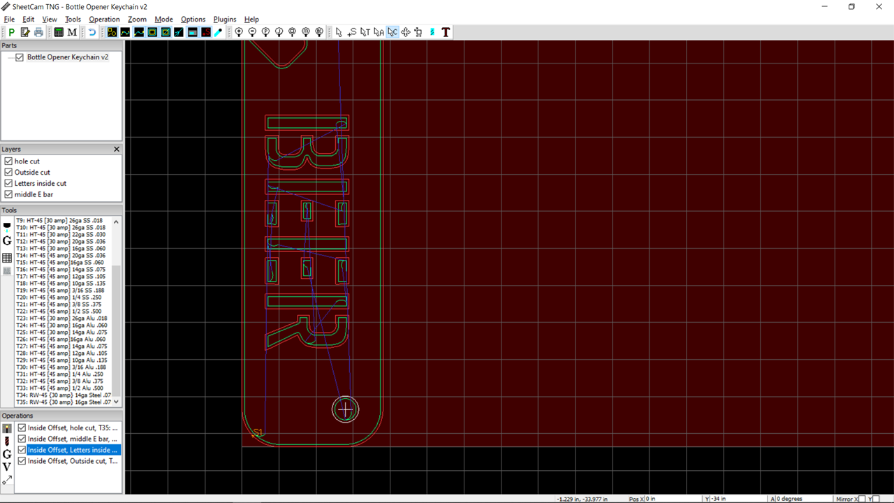
I define the hole cutting operation the same way as above. It turns out that it would have worked with the same parameters as the letter group but no big thing to have it as an extra operation.
Then I re-order the Operations so I’m doing the hole, then the middle bars of the E, then the rest of the letters and finally the outside of the piece. I just click and drag the operations in the box to the order I want. Then I run the simulation tool (the little icon on the menubar to the left of the T, looks like a drill bit).
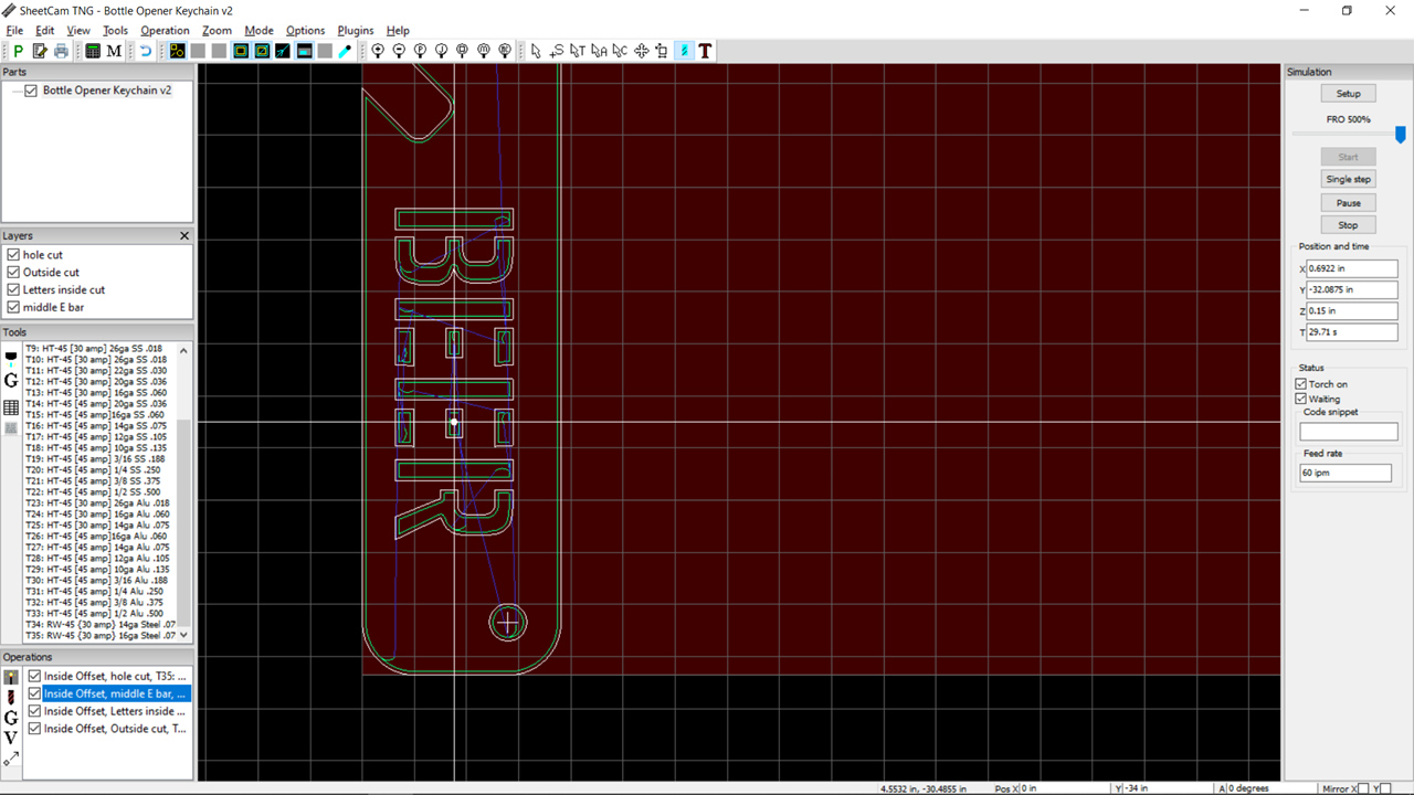
Everything looks good so I run the post processor and this is what I get.

The tool definition I have is for the “RW-45 {30 amp} 16ga Steel .075”. My naming convention is the Plasma name (RW-45), the power I want ({30 amp}), the material (16ga Steel), and the thickness (0.75). You can see a bunch of HT-45 tools defined in my tool set but those are all for the Hypertherm. I added a quick one for the RW-45 for this walkthrough. (And if you notice the steel thickness is wrong for 16ga - I had a 14ga one I created for something else and just copied it without changing the thickness of the material in my tool name ![]() ). You can use lower amperage than the tip is rated for so that’s not a problem even though I’d use the RW-45, you just need to slow it down vs using 45A that the tool can do.
). You can use lower amperage than the tip is rated for so that’s not a problem even though I’d use the RW-45, you just need to slow it down vs using 45A that the tool can do.
Hope this helps.
One more thing - if you use different colors in your design file, Sheetcam will not only set them to separate layers (the names will be the colors) but often can automatically select the correct offset, etc on the toolpathing saving you some of the steps above. But it’s not hard to take a design that is a single color (black in this case) and break it up for finer operation parameter control. If I wasn’t taking the screenshots along the way, this would have been about a 2 minute job to get this design ready for the Crossfire. ![]() Practice is good.
Practice is good.
6 Likes