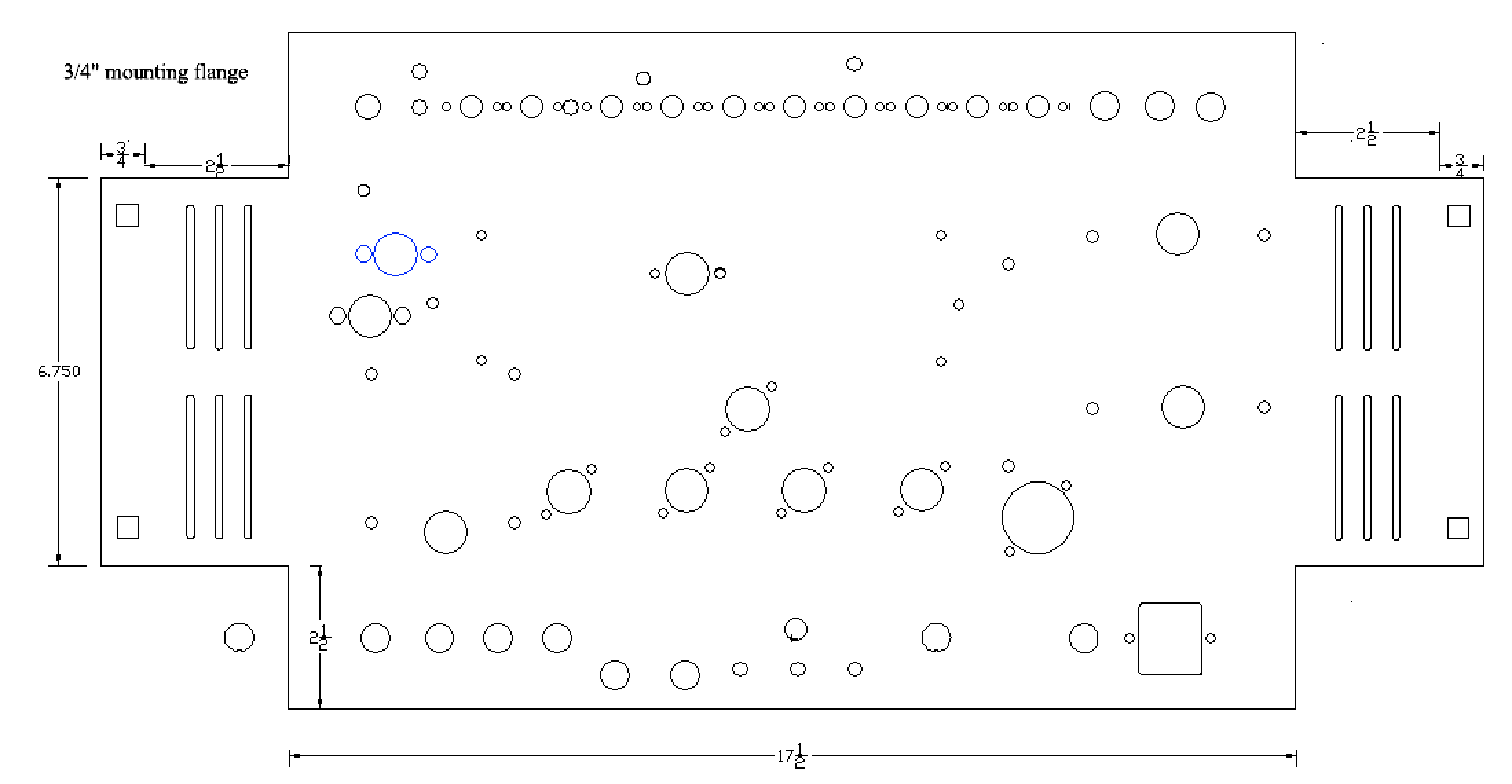
@Joel48, Note that I’m starting from a flat drawing, except with no bend radii accounted for, so I guess your great illustration above doesn’t apply in my case (does it?). Here’s what it was:
Now I’ve started altering my chassis drawing and in the process something else that is not 100% clear to me…
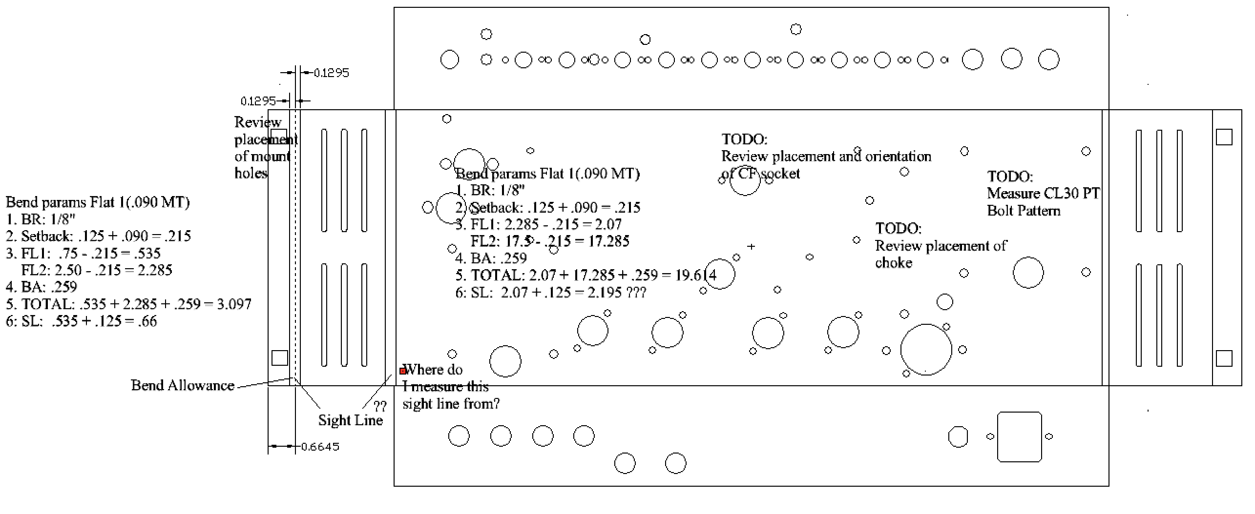
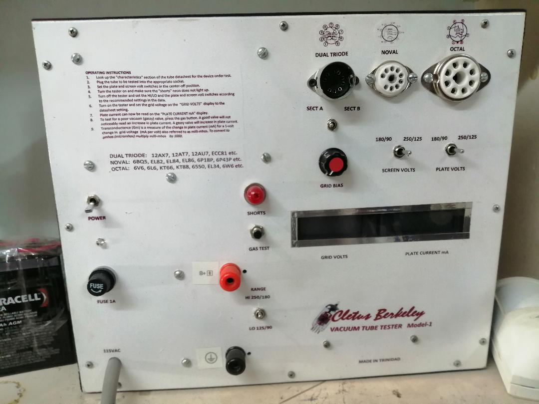
I started on the left end and fairly easily calculated the bend allowance and sight line for the first bend of the flange on the left (see the photo). Now moving on to calculate the left side (2.5"). Do I use the “adjusted” length (2.285") in the calculation of the flat, or the intended/mold length (2.5")? Also what do I base the measurement of the sight line on? Where does that start? The near edge of the first bend radius? Hopefully I’m making sense. I need to make sure that’s right because I’ll have to apply the same to the top and other end and flange.
I’m feeling ornery tonight so I have to ask why anyone is building Sheetmetal that has Tube/Valve sockets and, OMG, phenolic solder terminal strips!
Ok, I’ve got that out of my system… whew… ok so back to the discussion, I have to commend @Joel48 for his sage advice. It will save millions of minions who would otherwise pursue installing SW that is way over their head just to bend a bracket (no matter how ludicrous the application). Thank you Joel, you have saved many lemmings and educated a few of us hard nosed creatures.
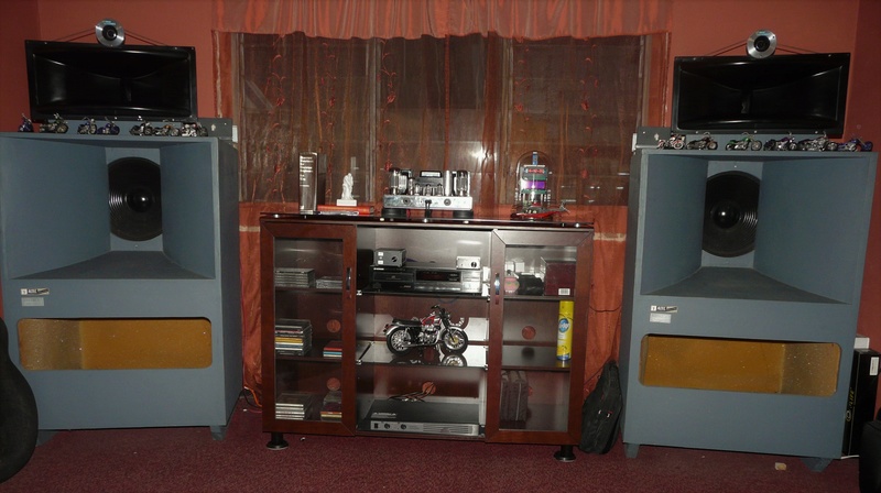
Two years ago I built me a Dynaco Tube Amp (4x
KT88 tubes) that SOUNDS ABSOLUTELY wonderful with my Altec Voice of The Theater speakers!
… With that off my chest, back to bending boxes!
Yes, thank you Joel!
I use solidworks on a daily basis (I design machines for the oil and gas industry) I’d be happy to help out if you want help with the dimensions. I can do the basic shell In solid works and send you the flat pattern.
You will always be using intended distances aka from the print. The bend radius never comes into play except when you empirically determine the K factor and even then, there is no calculation. Measure a flat piece, bend it to 90 degrees, sum both sides and subtract it from the flat length. That is the K factor or the amount of material gained.
Your first desired flange is .750, and the next flange is 2.50, so keep it simple.
To calc the length of the part:
F1 - K + F2 - K + the bottom of your chassis - K + F2 - K + F1. = total length.
To calc the slots, F1 - K + distance to the slot centerline.
I don’t know what sight lines are. You might be complicating the process, so keep it simple. Material thickness comes into play when you are given some inside-to-feature dimension and in calculating different corner configurations. In that case, you would need to add it to the calc mentioned above because flat patterns are always developed using outside dimensions.
Looking at your drawing, the first vertical line to the next line is .75. Now you have two lines. The first line is zero. The most right line is .75. Subtract the K factor, and that line represents the left side of the second flange. From that line, you can add features in the second flange.
Repeat the process to work your way to the far edge of the flat pattern.
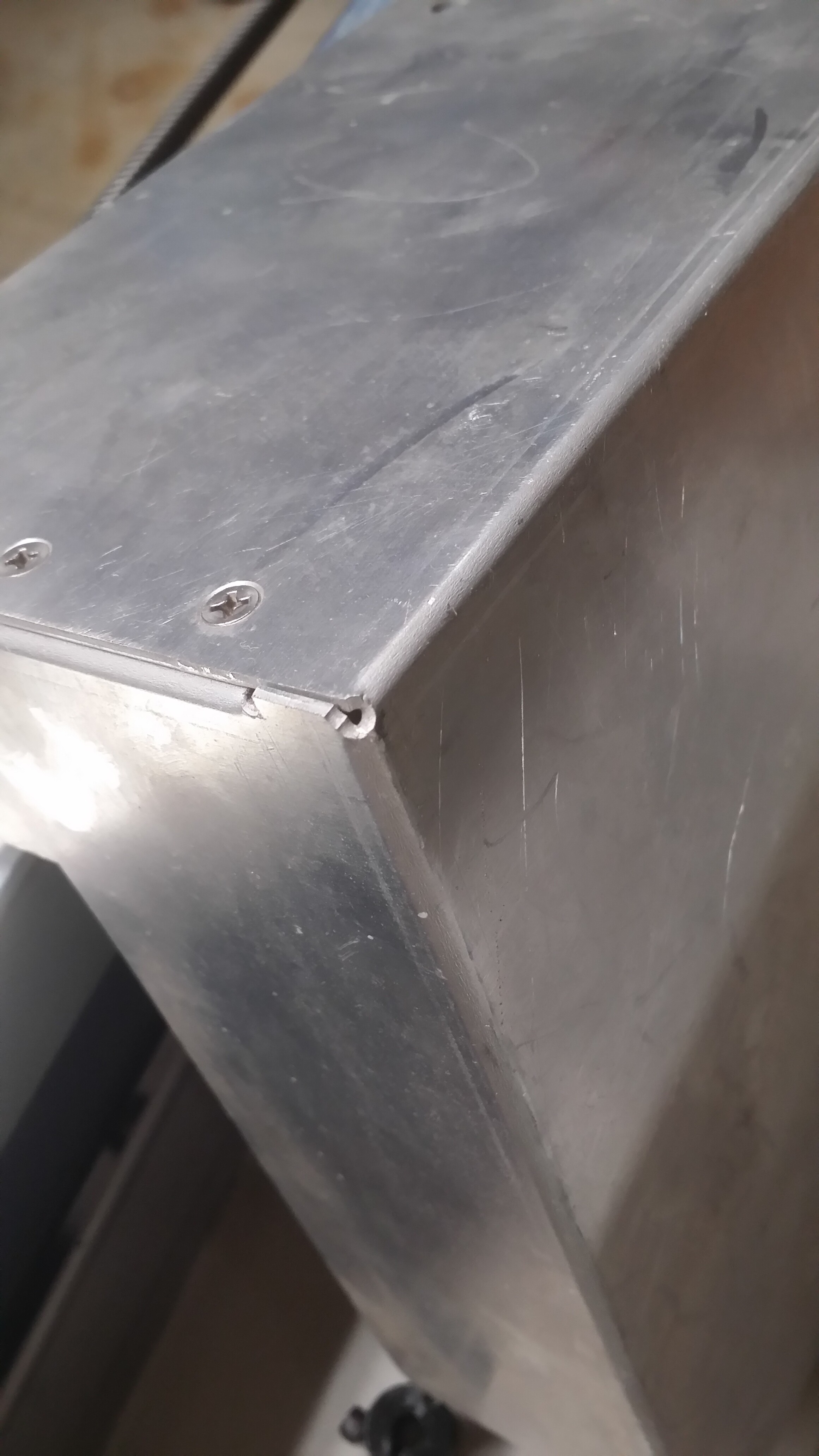
I found a part that has the corner hole I mentioned yesterday. It’s not as perfect as I said because I punched a couple of relief slots before the corner relief.
@Joel48 I think I’ve made the mistake of trying to combine too many sources of information. I got the notion of sight line from various references, this video shows an example: M Level 3 Bending Sheet Metal Proof - YouTube
I re-read your initial post about how to calculate the K factor by bending a sample piece of the material I’m working with, measuring and subtracting stretch. I think the video above is another approach to that, but I have to wonder if it’s wrong or just different.
According to that and some other references I’ve seen the sight line is for clamping the work piece in the finger brake for bending. How do you determine where to clamp the piece if you don’t use a sight line?
BTW, I like the idea of the bend refief hole. Will the Crossfire cut a hole that small?
I’m on vacation studying this so I’ll be ready to give it a shot when I get back to my shop next week, or I would have already tried some of this and had more context. Sorry for the vapor questions. I’ve learned a lot just from this thread though.
The M Level 3 Bending instruction is very good but from an Aircraft perspective. Precision electronic enclosures are easier to deal with because most if not all bends are 90 degrees.
I understand the sightline concept now. My perspective is from using a Press brake with a precision back gauge.
To your question “How do you determine where to clamp the piece if you don’t use a sightline?” I think you will want to figure a way to clamp a couple of stops to get close to perfect repeatability. You will not be happy with eyeballing the flanges. Holes that are to close to bends can drag the material in the direction of least resistance even in a press brake. I don’t think finger brakes have near the clamping forces as a press brake. I think those squares on the .75 flanges will be a problem.
Have you tried bending .090 over the length of your part? If your finger brake doesn’t have enough strength you can add some bending slots in the exact middle of the mole lines. Those are the two lines a K factor apart. I didn’t know what those slots were for until looking at some projects on this forum where guys bent some thick pieces with a vice and hammer. In your case, they would reduce the resistance of being bent but might add additional work to cover the slots after bending.
“Will the Crossfire cut a hole that small?” I don’t know! I’m still assembling my table so I can’t say what it can or can’t do. I’m guessing it is possible to pierce only and come back and drill the hole to the K factor diameter.
I like talking about this, but I am rusty. I retired 13 years ago so I have to dig to bring this information back to the surface.
BTW, I am an amateur intermediate Jazz Sax player and in the remote chance, you are interested in remote recording and collaboration or have an original tune you would like to add a Sax solo or something, let me know. Music is my other time consuming activity.
@Joel48 cool stuff regarding the sax playing. A friend and endorser Nicky Moroch is the guitarist for David Sanborn.
I wish I had time and inspiration to record, but I haven’t for quite some time. But it’s bound to come back around, I’ll give you a holler if I need sax!
@Joel48 I’ve been further examining your drawing example. Question, in the first image you provided dimensions, then the second one you delete all of the inside material lines. Do the 4", 2", and 1" dimensions remain the same in the subsequent drawings (eg, we’re looking at the full outter dimensions, just without illustrating the inside material thickness)?
@nolatone Hi Paul,
Yes, the dimensions remain the same because those are desired in the finished product.
Yes, the remaining lines represent the outside dimensions. They are the same as the isometric drawing in cases where there is one. The lines that are subsequently added are the mole lines, K lines, or bend deduction lines. All synonymous terms.
BTW, In reexamining my examples I realized I didn’t make clear what the material thickness is and the arbitrary K factor. The material is .100 and the K is .200.