I have TurboCad Designer ($79 software that doesn’t have sheet metal design capability, you have to buy their $1500 Platinum version for that), a Crossfire, and a Baileigh finger brake. I’m wanting to produce very small quantities of tube amp chassis pans out of .090 sheet aluminum. These are simple rectangular pans with mounting flanges on the end. Is CAD software with sheet metal capability REALLY a requirement?
Longer explanation:
For years I’ve been designing my Nolatone tube amp chassis creating a simple 2D drawing of the flattened chassis with all the holes where I want them and sent a dwg or dxf to a sheet metal fab shop to cut and bend them. I have no idea what they may have done in their software to handle the bend radius, K factor, etc. I’ve been using TurboCad Designer which has no sheet metal specific capabilities.
Now I’m moving all this in house. I’ve bought a Crossfire, bought the full feature SheetCam software, but I’m still using the same CAD software.
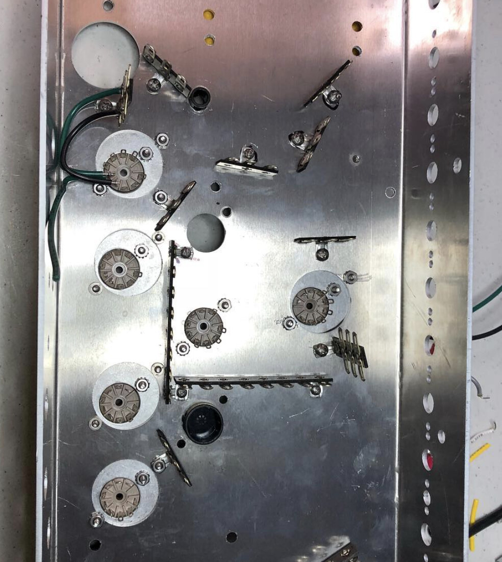
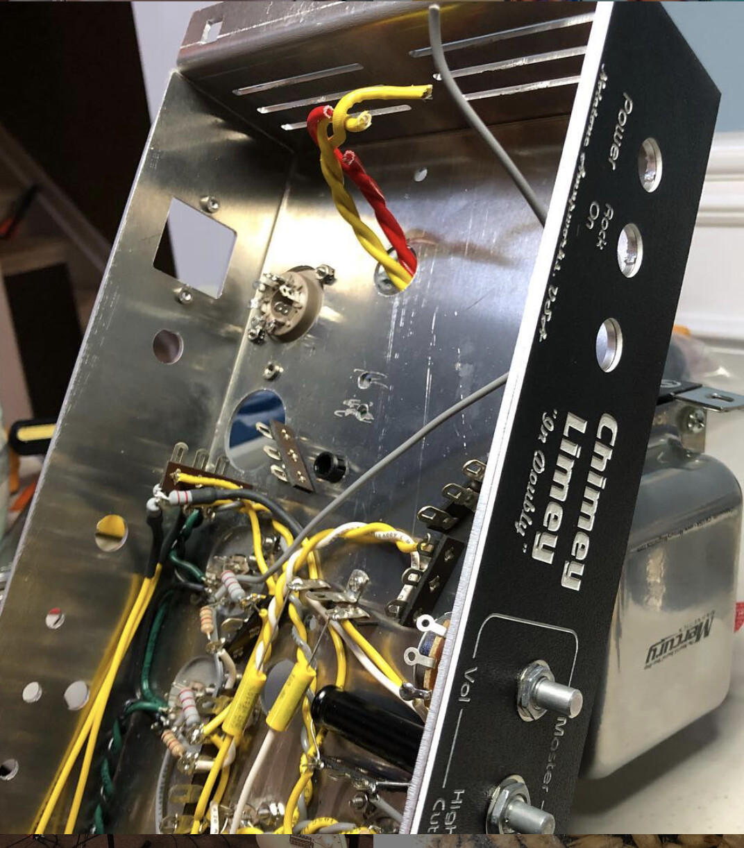
These chassis are very basic rectangular pan with simple mounting flanges on each end. Here are photos I pulled from Instagram to give you an idea. Note that these are both builds in progress so they have stuff attached to the pan:
After cutting I’ll be bending these boxes on a small Baileigh finger brake. I know I’ll need to account for some bend radius to assure the correct dimensions of the sides of the box and the mounting flanges.
It seems to me I should be able to just extend sides and flanges in the drawing to account for bend radius, and I can probably determine how much from measuring a previously produced chassis.
Is there more to it than that in my scenario? Is it really a requirement to invest in a software with sheet metal features and undertake the learning curve
When you bend a part the material stretches. So your flat part needs to be smaller than the finished part. Material thickness and bend die radius. Affect this stretch. Easiest way to figure out you exact stretch is to cut a small square blank say 3 x 3. Bend right down the center at 1.5" mark. Measure both flanges. Should = more than 3" you started with. This is how much your material stretches. Where I work we take half of that stretch from each side off the bend . For .09 and .1000 thick alum we use figure the strech is .1875 . For .8 alum we use .125. these numbers are rounded to the nearest 1/16 of an inch as our shop likes nice easy dimensions and we are not building space shuttles. The more accurate you measure on your test pc the better your finished part will be. Another thing every sheet will be slightly different do to tolerances on the sheet thickness and hardness from the mill.
Madman’s description of the K factor is spot-on, especially how to figure out what the number is for a given material, thickness, and inside bend radius. I owned a precision sheet metal shop for 30 years and that is the most foolproof way to get a precise number.
I didn’t understand the part about “taking half the stretch from each side of the bend” but just to keep it simple and, as Madman said, bend a piece of identical material, measure the length, bend it to 90 degrees, measure both sides and subtract them from the flat length. That is the amount of material you will gain.
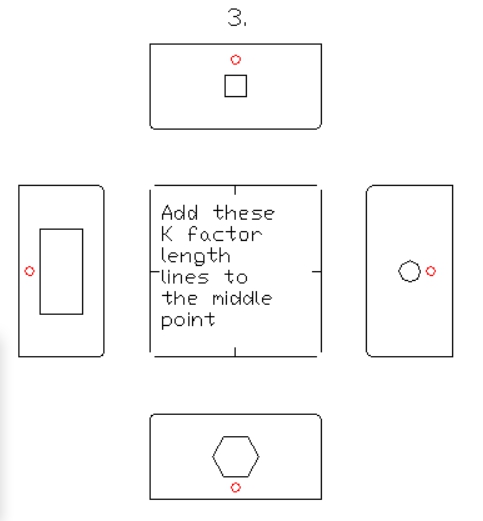
You don’t need another CAD software to do this. Draw the bottom of the chassis. Then draw each of the sides. Snap the sides to the bottom drawing but overlap by the K factor. You will end up with two lines a K factor apart. Let me explain that.
Picture you are looking at the inside of your chassis bottom and about to move the right side drawing as I described.
Snap a construction line to the lower right corner and then move it horizontally left the K factor distance. Then grab the right side drawing and snap it to the construction line. There are now two lines a K apart. The line that is most right represents the right side of the chassis bottom. The line to the left represents the left side of the right side drawing. You will at that point have effectively subtracted the material stretch but done it visually. Early on, I used to do all of my layouts mathematically but then CAD appeared and I realized the advantages. Later on, customers started sending CAD drawings making it even easier. All I had to do was disassemble their drawings and flip sides into a flat pattern.
Thanks @Joel48 and @Madman. Great info. I’ve been reading various bits about this from various sources. Am I understanding correctly that the drawing dimensions end up being slightly shorter than the actual dimensions of the final piece after accounting for K factor? I was not expecting that!
You are understanding correctly.
Example if you start with a flat piece 3" wide. And bend it down the middle of to form a 1.5 x 1.5 L shape. Because of k factor. The finished dims would be say. 1.5625 x 1.5625. so in order to get a true 1.5 x 1.5 angle you would need to substract a total of .125 from your flat pattern. So you would start with a 2.875" wide piece. It’s always best to test with scrap. Depending on break bending on the centerline may give you say 1.575 on one flange and 1.55 so you might. So once you figure how much material to remove from the flat. you may need to play with where you need to bend the part at to get your finished dimensions. It’s not hard once you figure it out. I say it’s not hard but I’ve been creating fabrication drawings for close to 30 years using board drafting and fancy 2d, and 3d software. 30 years what was I thinking .
Great answers here so I wont add to that in any way, but if you still find yourself wanting to try software checkout bendtech sm. Its available standalone for 300 bucks if I remember correctly and is a pretty powerful yet simple 2.5 D sheetmetal tool that you can export and load into sheetcam smoothly.
As the other answers say, it’s not strictly a requirement but it will take work to get it right.
You can also try DesignSpark Mechanical. It has a sheetmetal plug-in. I spent a lot longer dealing with Fusion360 changes of features & license permissions because it has a nice sheetmetal component. When I came across the same feature in DesignSpark I stopped using Fusion and haven’t looked back. You design without regard to the K-factor effect. Just make the sides and things the size you want. Then you tell it to “unfold” your part and it uses the settings for your material to apply the appropriate K-factor and shrink the part appropriately. No calculations on your part needed and because it’s in the model as the size you want, you don’t have an issue when you come back to an older design to try to figure out what the sizes were and where holes went, etc.
Ok…thanks!!! I’ll no doubt have to watch that one a few times for it to sink in… Still out of town for work too… Until the end of August… then it’ll be my time…!!
@Natemade I saw bend-tech as well and did a search to see if Crossfire users were using it but didn’t find much. Are you using it? I’d consider it if I knew it was getting the job done for people.
@jamesdhatch thanks for the tip on DesignSpark. I may give it a whirl, though if I’m going to switch CAD software I’d really like to do it in the Mac realm. I’m currently running TurboCad for Windows in a VMWare Fusion VM on my Macbook and I would really love to get away from that if at all possible.
It seems that if I take my time to fully understand the calculations for radius, setback, etc. it may make sense just to stay with what I’m using and alter the drawings as described by @Joel48 and @Madman.
I have made parts with it. I bought the software for tube bending and figured I’d add the sm module. The motorsports parts library was enough of a time saver to make it worth it for me. I have not used it to anywhere near it’s full capacity as all of my plasma work has been flat work. But I can vouch for the tube bending side of it that it is really nice to work with and I can also say iv cut multiple parts i exported out as a dxf and they came out well. Just never used the sheetmetal bending stuff
@Madman@Joel48 , I have what may be a stupid question (but if asking stupid questions bothered me I’d have died LONG ago)…
How do I measure the sides of the bent sample part accounting for the outer radius of the bend? Do I put a square across the two flats and measure edge of one flat to other flat on square?
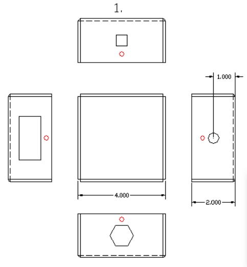
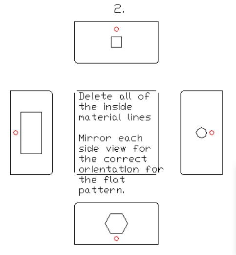
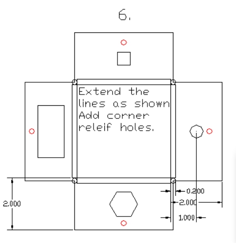
@nolatone Hi Paul. This is a visual of the process I use to make flat patterns from my customer’s DWG drawings. I was taught this by Walt Cook, the owner of Prippit Cam software for sheet metal fabrication. He was the creator of the first such software in the early '80s. The nice thing is any Cad system could be used. Anyhow, I think you can see the relationship of the lines when going from the isometric version through the steps of creating the flat pattern. I made the small holes red so the orientation might be apparent.
@nolatone I use a square to make sure the bend is at 90 deg. Then I use digital caliper to measure . All depends on accurate you need your part to be. The more precise you measure the closer you part will be.
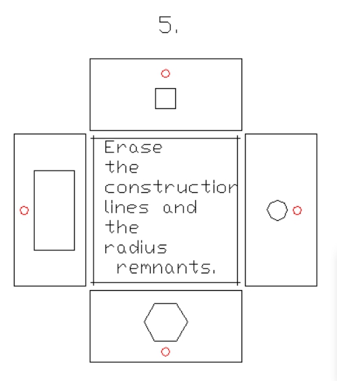
You are welcome. BTW, the corner relief holes are ideally the diameter of the K factor distance and located at the center of the intersection of the K factor lines. When the part is folded up, the result will be an inside to inside corner with a perfect circle in the corners. This type of corner is ideal for welding. There are of course other types of corners but you can figure those out once you are confident with the basics.
 what was I thinking
  .
.
 then it’ll be my time…!!