You will always be using intended distances aka from the print. The bend radius never comes into play except when you empirically determine the K factor and even then, there is no calculation. Measure a flat piece, bend it to 90 degrees, sum both sides and subtract it from the flat length. That is the K factor or the amount of material gained.
Your first desired flange is .750, and the next flange is 2.50, so keep it simple.
To calc the length of the part:
F1 - K + F2 - K + the bottom of your chassis - K + F2 - K + F1. = total length.
To calc the slots, F1 - K + distance to the slot centerline.
I don’t know what sight lines are. You might be complicating the process, so keep it simple. Material thickness comes into play when you are given some inside-to-feature dimension and in calculating different corner configurations. In that case, you would need to add it to the calc mentioned above because flat patterns are always developed using outside dimensions.
Looking at your drawing, the first vertical line to the next line is .75. Now you have two lines. The first line is zero. The most right line is .75. Subtract the K factor, and that line represents the left side of the second flange. From that line, you can add features in the second flange.
Repeat the process to work your way to the far edge of the flat pattern.
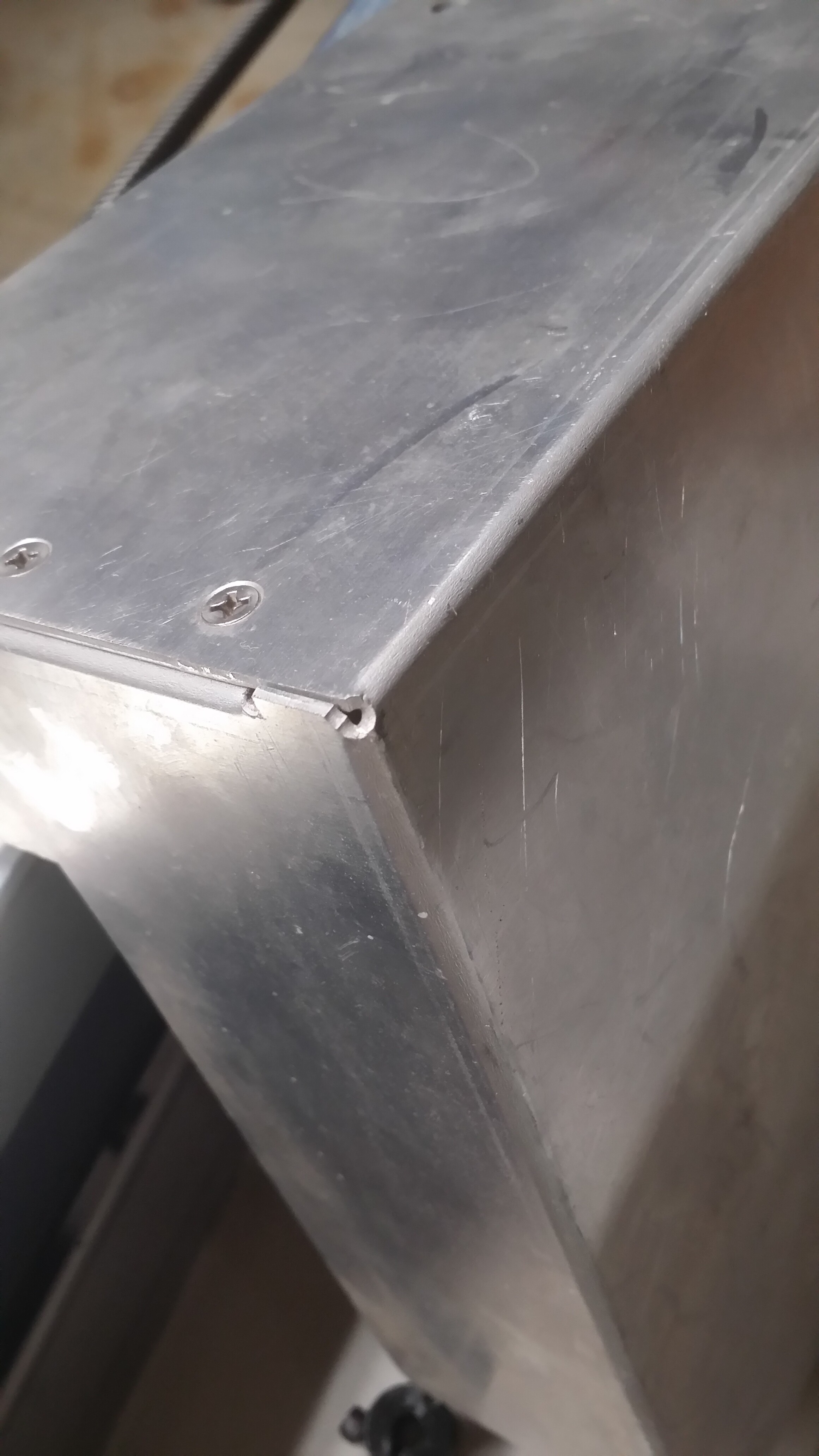
I found a part that has the corner hole I mentioned yesterday. It’s not as perfect as I said because I punched a couple of relief slots before the corner relief.
1 Like