Settings to improve small circle cuts - help, please

On mine, the entire red part that holds the bearing fell off the square tube. Those long screws that are awkward to insert thru the 2 inch square tubes had worked loose until the entire bracket fell. I then reassembled with blue loctite and had round holes for the first time.

I think I had the loose coupler with the stepper motor but that fix never fully succeeded in round holes because I still had this other issue, apparently.

2 Likes

That has to be a mechanical issue causing those severely out of round holes. Something in the Z or X axis is loose and/or the torch lead is pulling on the torch.

Loose couplers would cause lost motion. What is showing in that picture is excessive motion.

1 Like

Just finished putting a wrench on everything I could possibly touch. I have my table in a corner, closed in with curtains and vertical supports. Not a ton of fun crawling under it to access the backside of the machine. Nothing was particularly loose but there was room on a few of the allen bolts to torque down a little further. I see no real improvement. Again, I don’t get how the cuts are so inconsistent.

Does anyone have the tiniest bit of play on the torch itself? I grabbed it toward to the top and gave a little forward/backward pressure. Hardware all seems to be snug but there’s the tiniest amount of wiggle in the body of the torch.

Video

The amount of torque I’m putting on the torch here is way way more than the machine would ever put on it. It could be a non-factor.

The ‘movement’ looks normal to me, no issue with holes here.

I was referring to a lateral movement on the Z axis assembly.

Cut out a square, with two circles in the middle. The many circles next to each other is wasting more material than necessary.

Do so at each part of the table (top left, top right, center, bottom left, bottom right).

Measure your square cut outs, and look for hole irregularity.

I say this because something could also be either out of square and/or binding in one particular area of your table.

Cutting small holes it is hard to watch all the movement. Are you watching the cuts to maybe see if something is catching? Could be slag causing missed steps in a extreme. I don’t see that issue .

You could possibly slow the cut speed way down with a dry run and a pencil taped to the torch. That way you can watch in a easier to watch speed for a issue. That would eliminate slag and see if it can draw round holes.

Also have you maked all lead screws and coupling including motor shafts to look for slippage? Torquing the down can cause them to strip. I figured that out the hard way.

The pencil idea is a good one, I’ll try that!

I haven’t marked the screws and couplers, I can try that as well.

1 Like

I don’t know if I have these lined up in the correct order that they cut but when you look at it this way, the consistently terrible holes occur when the lead-in is starting in a unique position relative to the other four holes. This is suggesting some forces on the torch cable or direction of the gantry that accentuates some excessive movement. Try to re-CAM the sample with the holes being started all in a similar clock position around the circle. With the orientation it presently sits in my diagram the two worst holes start at 6 o’clock and 4 o’clock. 10,11 and 12 o’clock seem to be the best starting locations.

Have you tried switching to new consumables? I would create a 1" circle and cut see if it comes out round.

I had this thought as well. I thought the second test was with all starting points moved to the same location, but now I’m questioning if I did make the cut once I’d made that change.

No time to mess with it this weekend unfortunately, but I’ll have time tomorrow.

I can easily enough. They looked to be in fine shape when I checked them before these cuts. I also keep in the habit of cleaning any debris off the end of the nozzle (unshielded in this case) before each new cut.

But thinking on this now, it is possible there is something inside the nozzle hole. My cleaning is typically running the nozzle (or shield tip with standard consumables) against a flat piece of brillo pad to clean it to bare metal.

Crud being stuck on your consumables can cause an irregular cut, but not a consistent defect.

You have displayed a consistent defect.

What you haven’t mentioned is if you have tried cutting something simpler in 5 areas of your table.

This will address whether it’s an issue in just a certain area on your table, or if the issue occurs randomly all throughout.

As for debris, this can easily be remedied by replacing consumables - this is a practice often suggested right away as part of any troubleshooting.

I’ll try the 2 circles in a square tomorrow around the table and report back.

Did some testing today. Before jumping in to that, I cleaned the crap out of the whole table. Scraped the water table, wiped down all the surfaces, cleaned and lubed bearings.

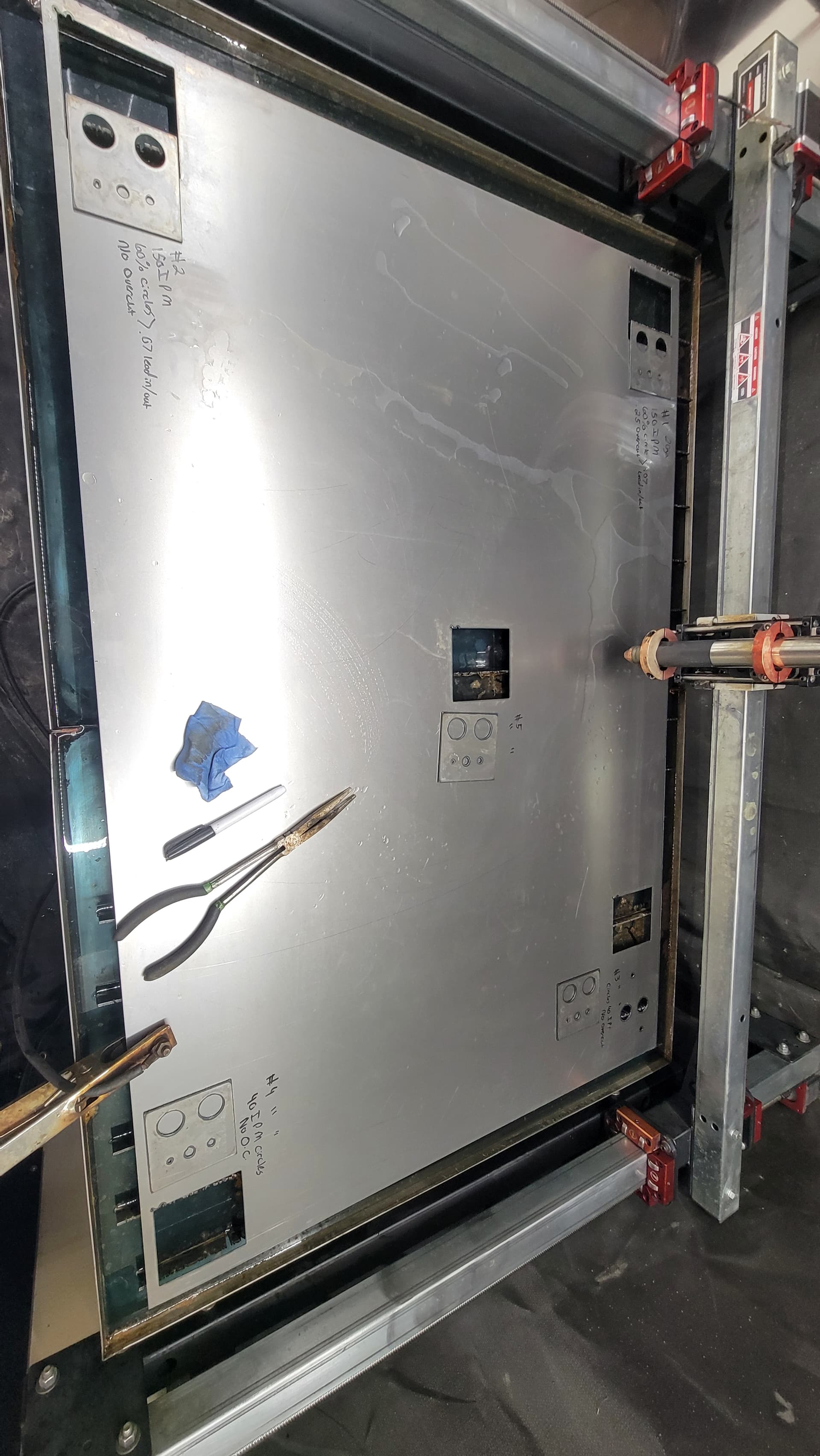
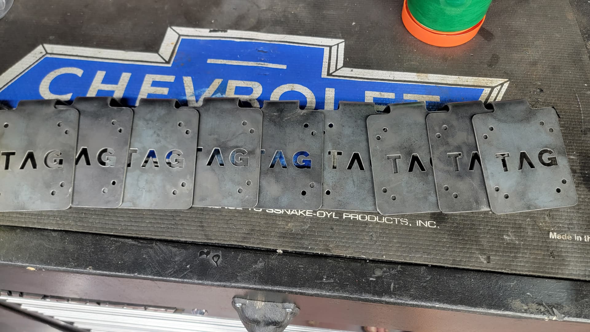
Here’s what we got on a piece of 20ga steel. Test #1 was top left of sheet, #2 was bottom left, #3 was top right, #4 bottom right, #5 center.

All cuts done at 27A, 75-80 PSI of clean dry air (replaced dessicant beads in pre filter, table filter still all blue) new standard consumables.

Cut #1, 150 IPM for square, 60% reduction for circles, .25" overcut, .07 lead in/out on circles

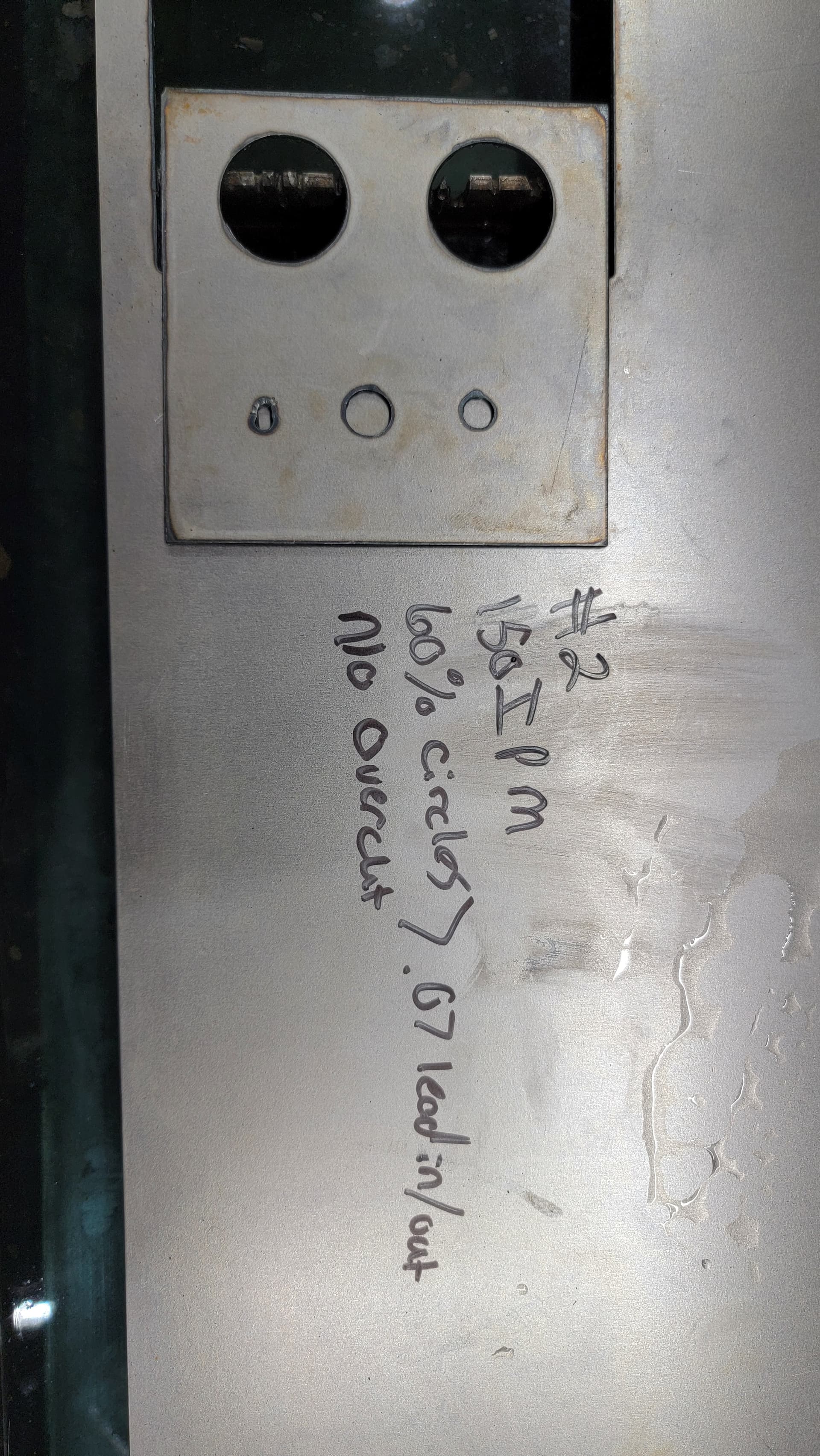
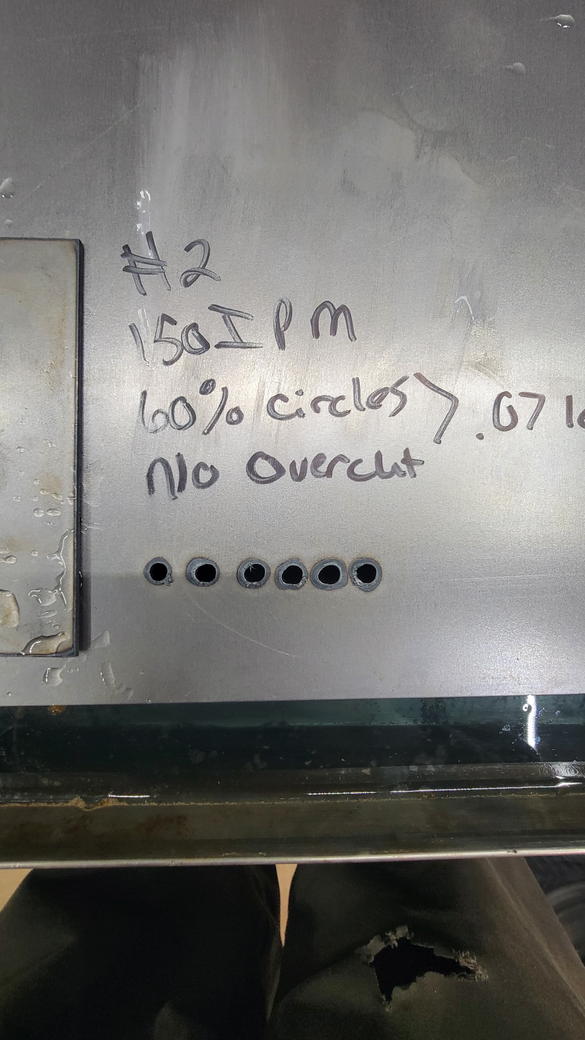
Cut #2, 150 IPM on square, 60% reduction on circles, .07 lead in/out, no overcut

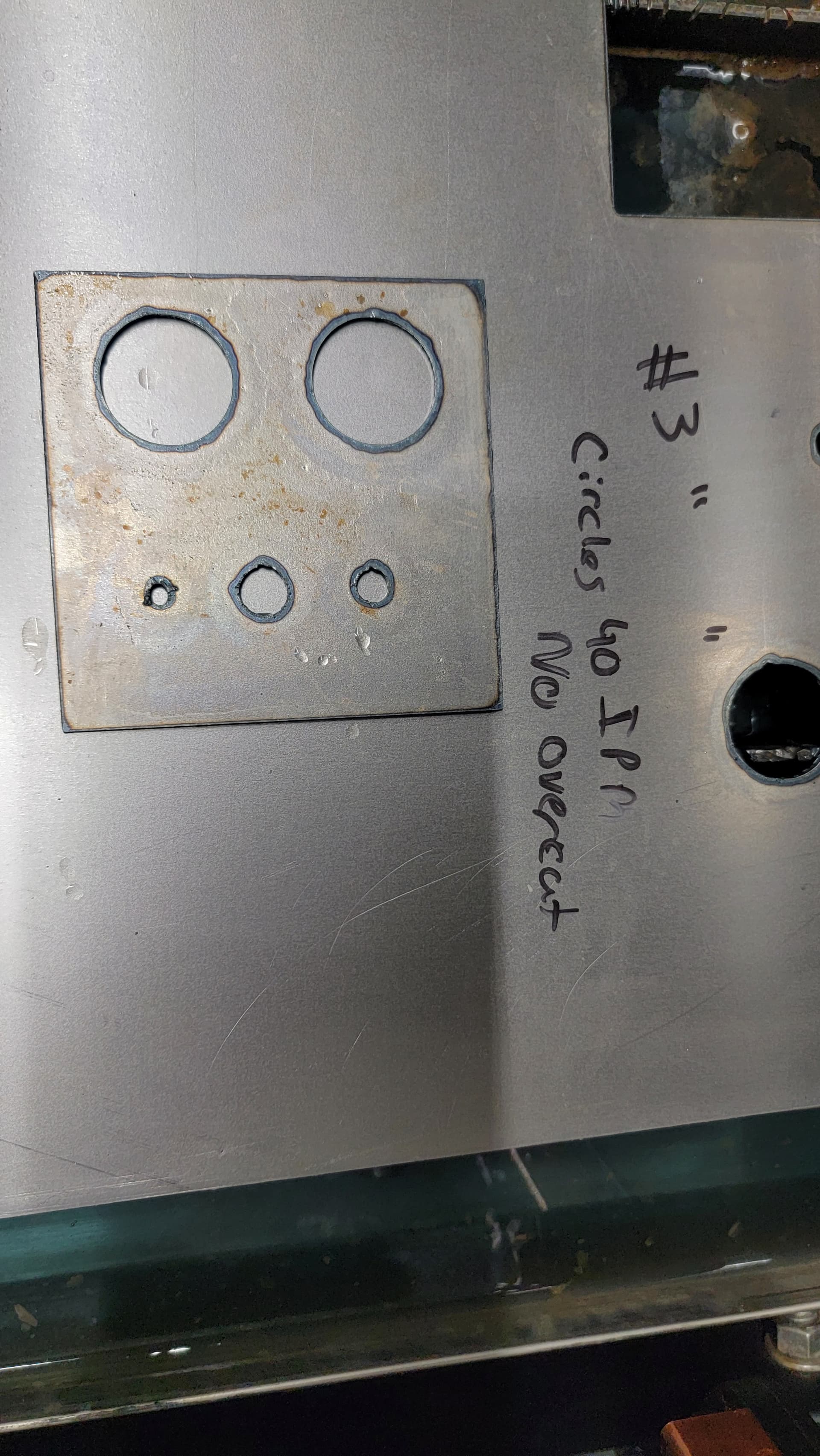
Cut #3, All else the same, 40 IPM on circles, no overcut

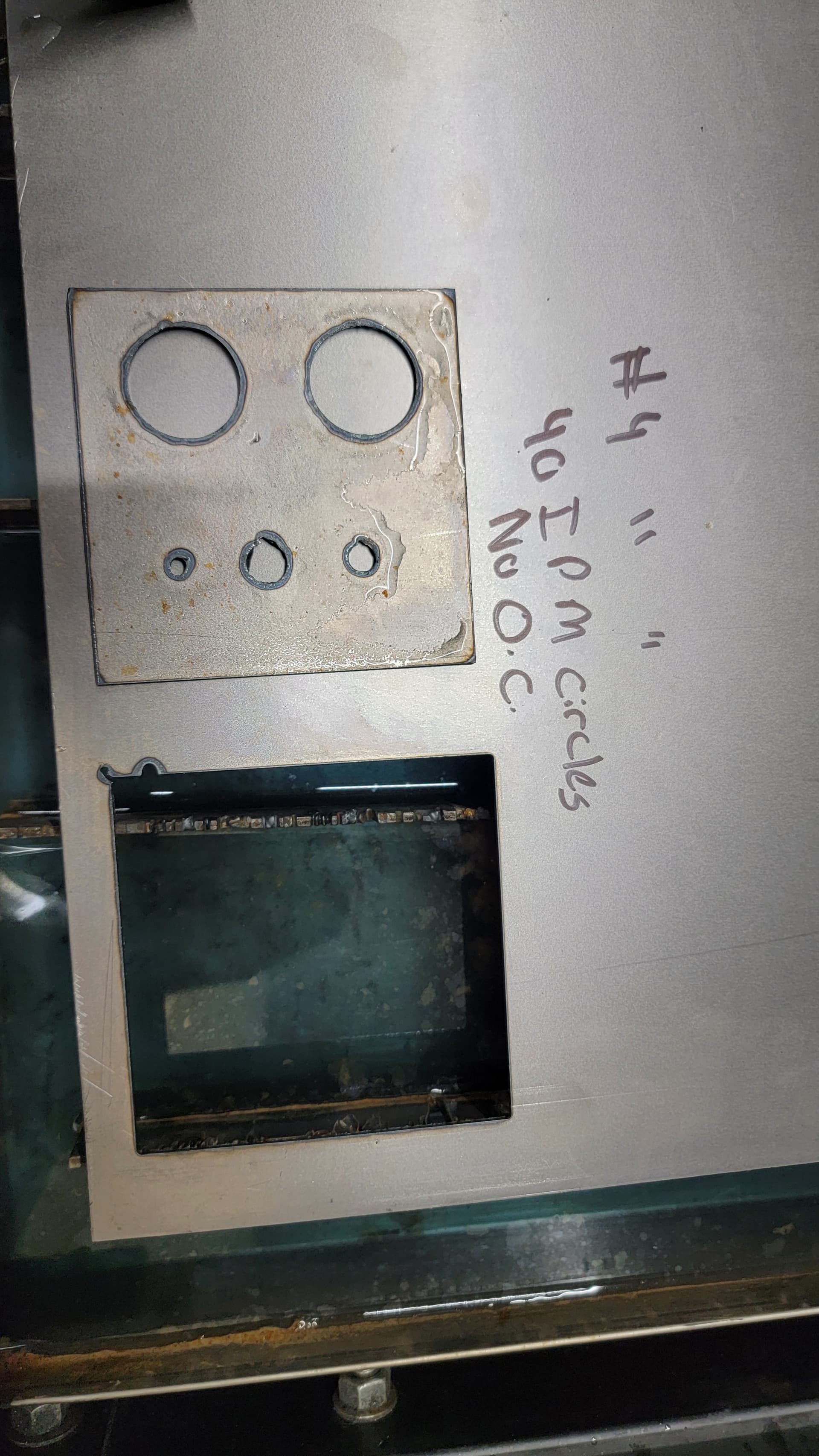
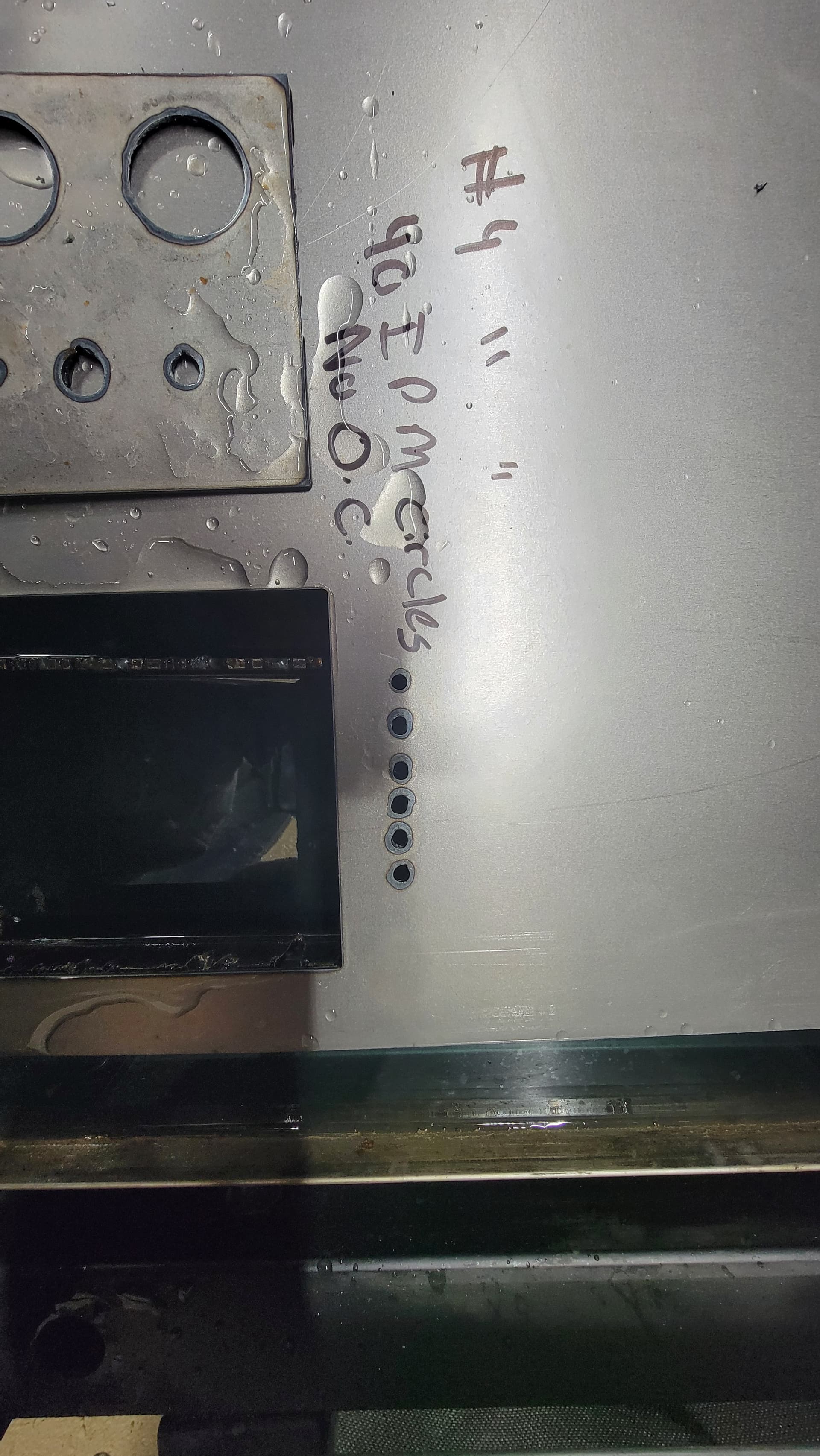
Cut #4, All else the same, 40 IPM, no overcut

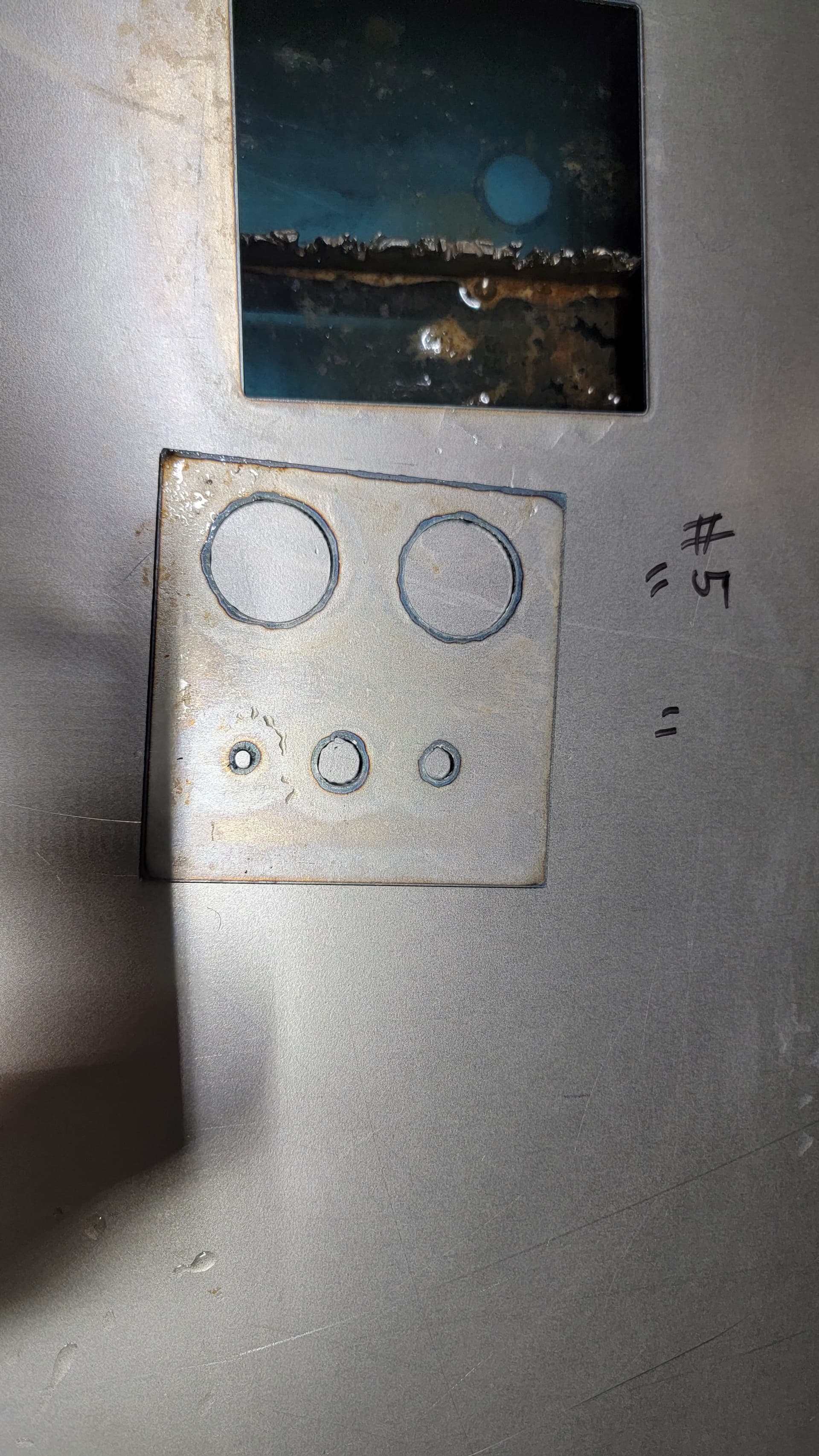
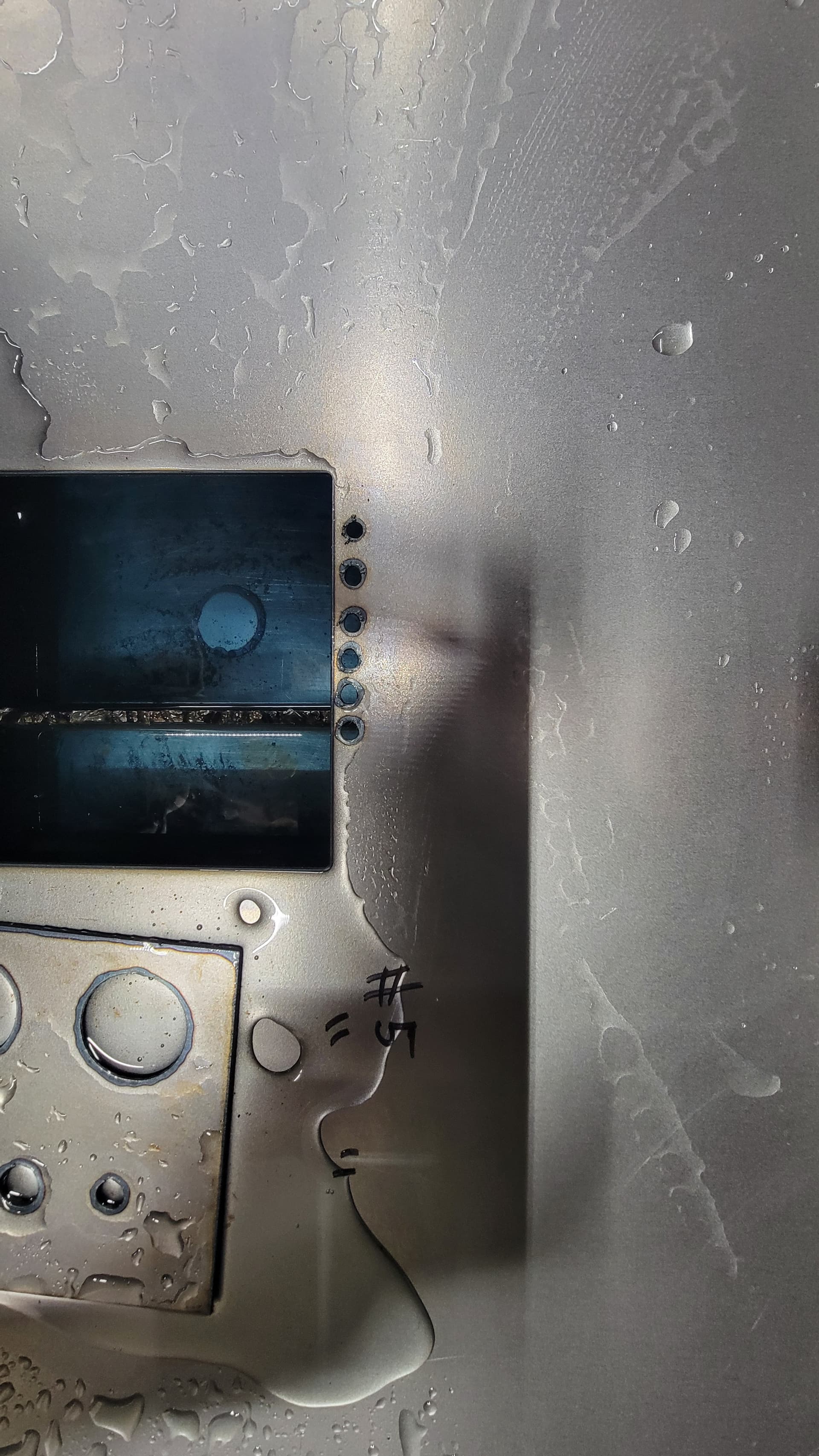
Cut 5, Identical to cut #4

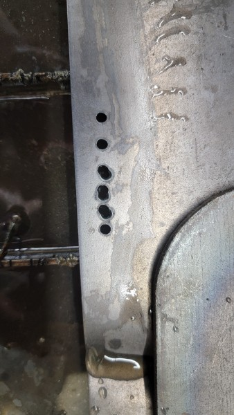
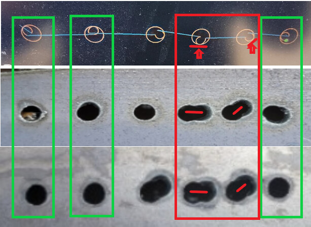
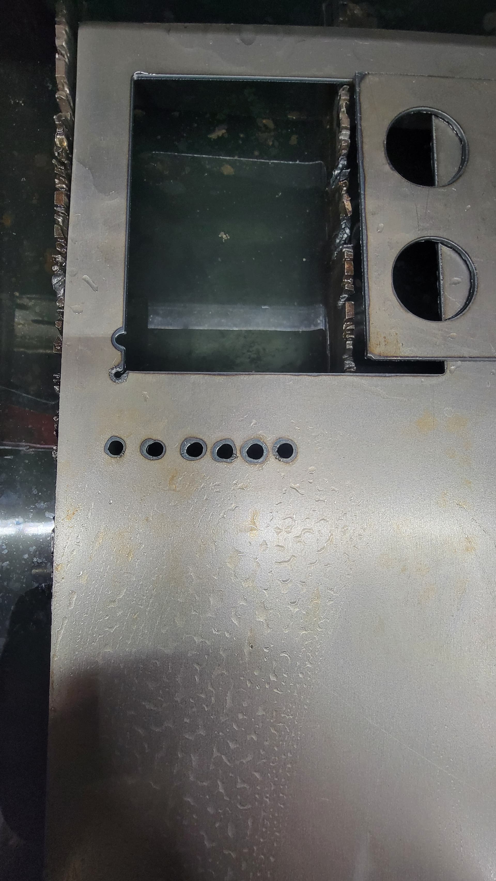
After doing these tests, I did some small circle tests in the same 5 locations. These are the results. All circles had the starting point in the same place. All cuts were the same collection of settings.
1st circle: 100IPM, no overcut, .07 lead in/out
2nd circle: 100 IPM, no overcut, no lead in/out
3rd circle: 80IPM, no lead in/out
4th circle: 60IPM, .07 lead in, no lead out
5th circle: 40IPM, .07 lead in, no lead out
6th circle: 40IPM, no lead in, .07 lead out
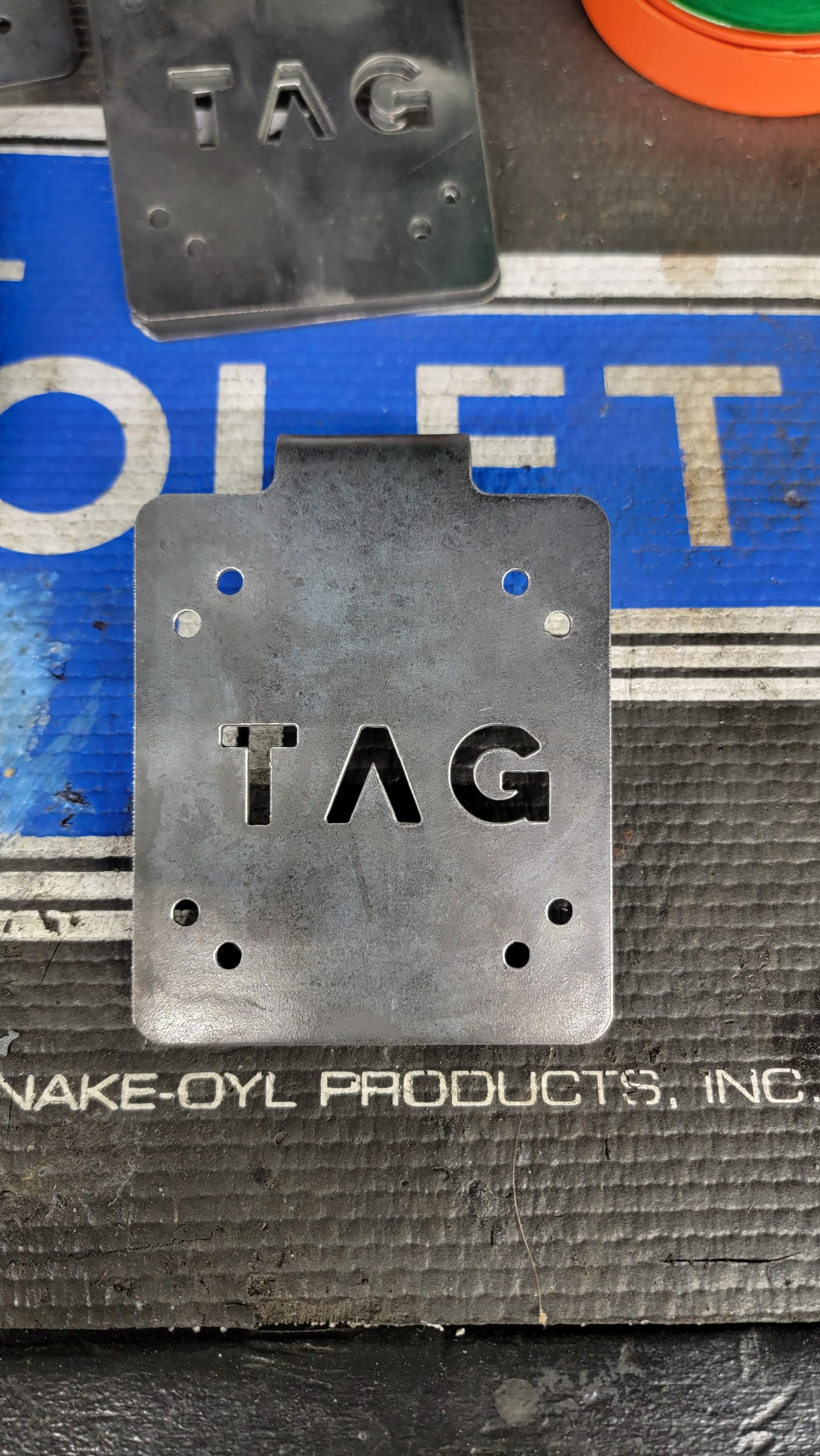
Cut #1,

Cut #2

Cut #3

Cut #4

Cut #5

It would seem the table likes faster circles, even small ones. I watched the torch during all cuts, can confirm the X and Y seem to move smoothly with no jerkiness visible to my eye. Still, a good bit of inconsistency.

2 Likes

Ok now we’re talking thorough, hell yeah!

Now others will come in and correct me, but in my few years of doing many parts (using holes that required accuracy) I will share this -

At gauges such as 1/8" and thinner, I never slowed down even for a hole for say, 3/8" diameter or slightly smaller.

I would only ever begin to adjust my feedrate for small holes if the metal is at least 10 gauge or thicker.

This is to ensure all material is burned away and giving me a cutout that’s acceptable to what’s in CAD.

For example, I run about 48ipm to achieve a 0.625" hole within .003" on 3/16". As for the remainder of the cut, it’s all done at 70ipm.

If I run the same 70ipm for the hole, I would get something closer to 0.610" or so with a bit of tapering.

I don’t know if the other guys do this or not, but again I only run slower on thicker material. But thin stuff? Always at base speed.

Here’s 16 gauge with some holes, all done at 150ipm.

1 Like

At 60% speed reduction on the holes, fire control should disable the THC. Have you verified that is the case?, at least I think the threshold is 60% of the main program speed.

I think you have already covered most things Hypertherm mentions below… They pay extra attention to how important the THC is, hence my comment above and a few other google search’s say make sure THC is off.

How to cut better plasma holes!

It should. It is all based on what is set in this THC dialogue box in FireControl:

1 Like

I’ll confirm the THC cut off. Out of the shop for the time being to get dinner going.

I ended up cutting out 10 pcs of a bracket I’ll be listing on my site. If it was a visible hole I don’t know if I’d run it, but it’s a mounting hole and IMO, plenty round enough for its purpose. This is on 12ga steel. 40A, 90IPM (including holes) 4.5mm holes, .07" lead in/out.


2 Likes

When you say reduction in speed, are you setting that up in sheetcam using rules ?

If you change the main program speed, for testing purposes, Fire control will not see a difference between main program speed and slow down speed. By using rules, your main speed stays as per your tool speed, for doing outer cuts etc and the hole speed is reduced based on the rule, triggering FC to see a speed reduction and turn off the THC.

Same principle can be used for 90 degree turns on corners or even more acute angles can be set differently, all depends how far you want to dip you toe into rules.

Yes, I would be satisfied with those brackets.

1 Like

That’s correct, 60% reduction set in SC.