I occasionaly get jobs where customers want me to remake a part that they can not find anymore. often times it involves a flange type of part with holes that need to match up. i fully understand how to scale an object. but it seems like every time, no matter what, if there are holes in the part, after it is scaled the holes are no longer where they need to be. ive attatched a part for example. any help would be greatly appreciated. as this is causing me issues constantly.
austins part_0001.pdf (318.4 KB)
Have you tried using constraints to set relationships with other features of the object?
1 Like
i have not. i will look into that as i am not 100% sure how to. but i am pretty familiar with the program at this point so it shouldnt be too much
How are you scaling the part?
creating a point near my part. measuring the part, and using sketch scale. is there another way ?
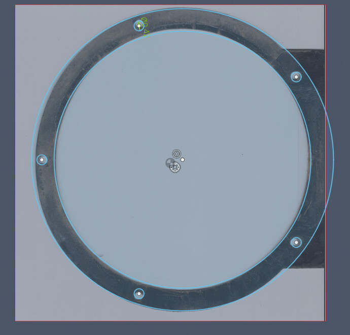
If you import your image as a canvas, then you are able to calibrate. You pick two points on the bracket and measure and then pick those corresponding points on the canvas.
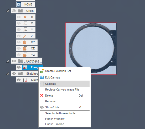
You can then start your drawing over top of the canvas. That relies on a very good, straight on picture such as a scan on a copy machine or printer.
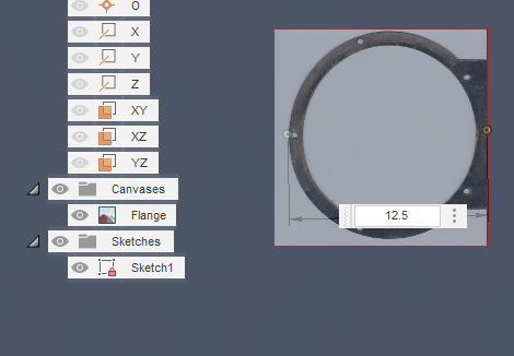
Type in your value. I pick 12.5. It becomes very large and I need to zoom out to get it in the frame but those dimensions will remain 12.5.
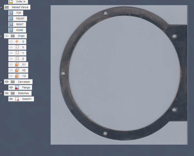

Then you can start building your sketch around this and verifying your measurements.
- In this case I started with a 3-point circle, which helps you find the center, for the inner circle.
- Next, your outer circle starting in the center (determined by the inner circle - this will "constrain those two circles together. This ties them together: you could still vary their sizes but they will remain concentric with each other.
- Now put one circle on a hole and create a circular pattern using that one hole. After your pattern is more clear, you can move that one hole around and see how it affects the others. When you get it really close to the image, measure your bracket in relation to your drawing. By using the center point for the circular pattern, you “constraining” the bolt holes to the center of the other holes.
.
Another way is to make sure that you “constrain” other measurements, like Bret mentioned earlier. Those will be things that you know need to be unyielding. Those constraints need to be a set size to fit in a particular location such as the location of the bolt holes/size/relative location to one another. In most cases, constraints are simply dimensioning a hole, a side, the outside of the rim, the inside of the rim. Any measurement/dimension will become a “constraint” if you type in the number.
2 Likes