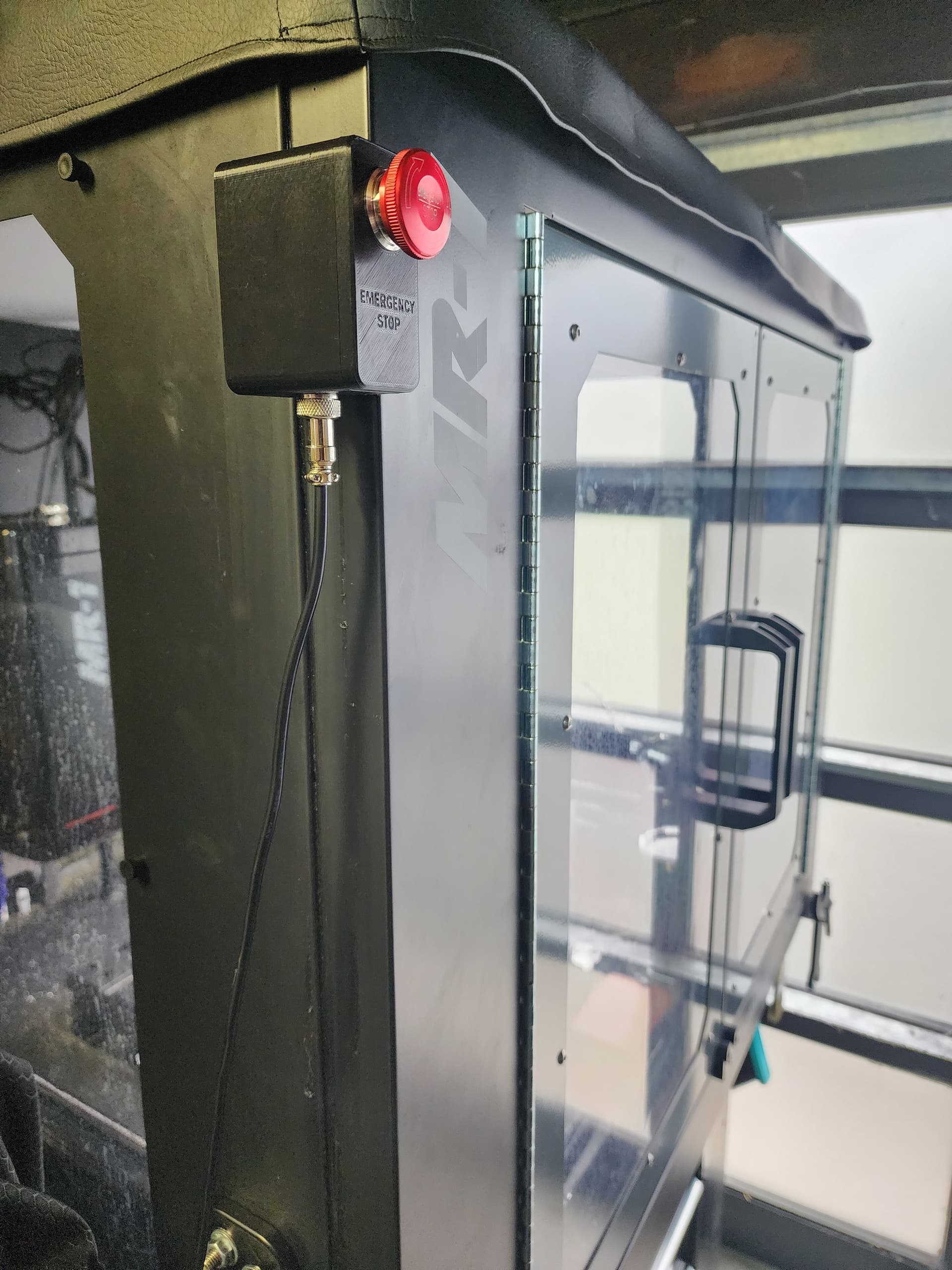
I made a wired remote emergency stop, that can be used either handheld or magnetically attached to the machine. Here is the build process.
Materials - Total $64.21
- (1) 3D Printed Enclosure | MR-1 Emergency Stop by CaliPrinter - Thingiverse
- (1) 22mm Stop Button | Amazon.com
- (1) GX12 2-Pin Aviation Cable (2m) | Amazon.com
- (2) Set of GX12 2-Pin Male/Female Aviation Connector | Amazon.com
- (2) 1.3" Square Magnets | Amazon.com
- (4) M3 Heat-Set Insert Nuts | Amazon.com
- (4) M3x16mm | Amazon.com
- (2 feet) 20 Gauge Wire | Amazon.com
- (1 inch) 3/32nd heat shrink
Tools
- 3D Printer
- M2.5 Allen Key
- Wire stripper (can use side cutters)
- Side cutters
- Soldering Iron
- Heat Set tips for the Soldering Iron
- Heat gun/lighter
- 1/4" wrench
- Lead-free solder
- #5 flat blade driver
Steps
- Print the enclosure. Infill and layer height doesn’t really seem to matter - use whatever settings float your boat. The file can be found linked above, and on Thingiverse (Item #6495466). I used 20% infill, and 0.3mm layer height, which came out fine.
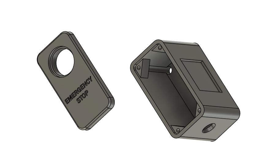
- Use the soldering iron with the insert tip, and add heat-set inserts into the 4 holes in the cover.

-
Superglue magnets into the enclosure
-
Wire the box.
3.1 - Secure the yellow wire (unused) inside the box. Run the blue and green wires through these components in the following order: aviation connector nut, aviation connector washer, small hole in the enclosure, heat shrink, aviation connector terminals.
3.2 Solder the blue and green wires into the female aviation socket. Slide down the heat shrink and heat to secure over the terminals. Push the socket into the enclosure, and slide down the washer and nut.
3.3 Using access holes on the back of the enclosure, run the 16mm M3 machine screws through the rib holes. Push them far enough that the end of the screw is flush with the top surface of the rib, but no so far that they are protruding past that mating surface.
3.3 Separate the E-Stop button from the nut, run it through the box cover, and secure with the nut. Connect the E-Stop button with the blue socket (make sure that the socket is oriented correctly - note the metal terminals). Put the cover onto the box, tighten the M3 screws to finger tight (approximately 8 in/lbs).


-
Wire the Controller
4.1 Unfortunately, I should have, but did not, take pictures of this part. It is very simple. As this is a safety item, verify all wire colors and logic prior to running an operation. For note, my machine was wired such that the circuit is “normally closed”, and when the E-Stop is activated, the circuit opens to disconnect power. The idea is that the new E-Stop is added in line with the existing E-Stop, so if either is opened, the power will disconnect.
4.2 Remove the control box cover. Locate the 2 terminals on the rear of the factory E-Stop. The wires are secured by a #5 flat blade cap head screw. Loosen the screw, remove the top wire.
4.3 Punch out 1 plastic cover for the expansion (EXP) ports in the rear of the control box.
4.3 Collect an aviation connector socket, remove the nut. Run one of the disconnected wires through the nut, some heat shrink, and through the open expansion port. Solder the wire into the aviation connector terminal. Slide down the heat shrink and heat it to secure.
4.4 Take the 2’ of 20 gauge wire, strip and solder into the second terminal of the aviation connector. Run the loose end through heat shrink and the nut. Slide down the heat shrink over the terminal, heat to secure.
4.5 Insert the aviation connector socket into the expansion port and secure it.
4.6 Secure the open end of the 20 gauge wire into the open terminal of the existing E-Stop. -
Connect a male aviation connector to both ends of the cable. Use the cable to connect the E-Stop to the controller.
-
Function test and enjoy!
