Red Arrows in outer space Need help with Contour Selection

These red arrows are ridiculous. I can’t tell when it will cut inside or out because it puts the red arrow out in space, seemingly unrelated to the are I am trying to cut…
Can you help me understand which of these is inside and which is outside, and how to tell the difference?

the c shape make it harder to see .

look at this example

the toolpath is developed on the same side as the arrow.

inside


Outside


Maybe something about my settings makes it more difficult to see? Could it be because I extruded the sketch then went to create the tool paths?

Is the arrow placed relative to the line I was closest to when I first placed it? so in my example, the red arrow is relative to the outside curve of the letter C?

If it’s on a line then it’ll be which side of the line that arrow is on is the side of the toolpath will end up getting created.

But you typically have a central line tool path when cutting a straight up line so it’s kind of a moot point.

Your first click on it would likely automatically make it cut out the inside hole first because it does face detection.

You can always generate it to a path to double check.

The shape of the c itself is making it weird ,optically .if it was a rectangle or any other shape I’m sure it would be very obvious

its not just the “C” other small shapes have the same problem, such as the detail on the butterfly on the GNOME hat in this thread.
There has got to be a better way to select contour lines - Software / Fusion 360 - CAM - Langmuir Systems Forum

Maybe Fusion is just not the right program for making tool paths. You cant see what it will do until you commit to a step that renders the work you did creating the tool path not editable… The typical advice is to zoom in, but even at max zoom then the arrow is not placed on the screen so thats no help either. Surely there is something better or better way.

The problem that we go through with the gnome hat is a different problem. The gnome we’re dealing with contours that will not generate tool paths because of it all not being able to fit in the smaller geometry.

Is the problem you’re having that you’re not able to generate toolpaths at all for some of the shapes?

One is whether you’re selecting the inside or outside of geometry which 99% of the time is not a problem because you just create from selecting your extruded face and an automatically figures all that out.

Isometric view can sometimes give you a little bit better view if you do feel like manually selecting all your contours.

Every aspect of the tool path is editable after the fact.

The only time I ever come across needing to manipulate the arrows is with single line cutting.

If you were design is already extruded your first click which produces the red arrow should put the arrow on the correct side automatically because it is aware of what is inside and outside.

How many separate tool paths are you creating for your design?

Humm… I missed something important.

So you can finish generating a tool path, preview or simulate it and then go back and switch one of the red arrows to the other side? That would be huge.

To answer your question, no it creates the tool path for the letter “c” I just struggle with the edit process, but maybe you have given the answer in that every aspect is editable…

I just extrude the part to make it a couple mm thick and then when you are planning a tool path choose individual lines and inside/outside becomes redundant.

1 Like

This essentially was the key to moving forward…I dont know how I got it in my head that I could only delete and re-create them…I still think the red arrow stuff is really dumb, but really appreciate the help!

I think there’s a video out there somewhere that says that toolpaths are not editable. I too labored under that misimpression for a while until I saw the toolpath out of date warning/message and was able to regenerate it. I think you saw it somewhere and it stuck in your head like it did mine!

wait. What? How does one edit the Toolpath after it’s generated? I am struggling with linking issues like mad and the time it takes to re-select contours is killing me. I agree those red arrows are awful. There’s no way to tell often whether you’re inside or out. I am manually selecting all my contours. So there is some little bit of knowledge I’m missing it seems that would unlock a huge increase in speed for me it seems.

A lot of my designs are really tight, yet I believe they are cuttable. Is it possible to start a cut on the inside to hide the pierce, but then actually travel around the outside? My paths fail choosing inside, or don’t travel the whole part. This creates linking errors. So for instance, Imagine a thin half-moon shape. Going inside it stops far short of the ends. Going outside cuts the entire shape but the pierce shows. I’m using no lead-in angle, .05 lead-in distance. Why won’t the software allow the torch to travel over and back across the same space? It would be cutting empty space, after all. What about a straight line? Just pierce and go, instead requiring a full loop?
I don’t want to hijack the thread but understanding the way that the Cam software works regarding loops and paths is the problem originally raised.

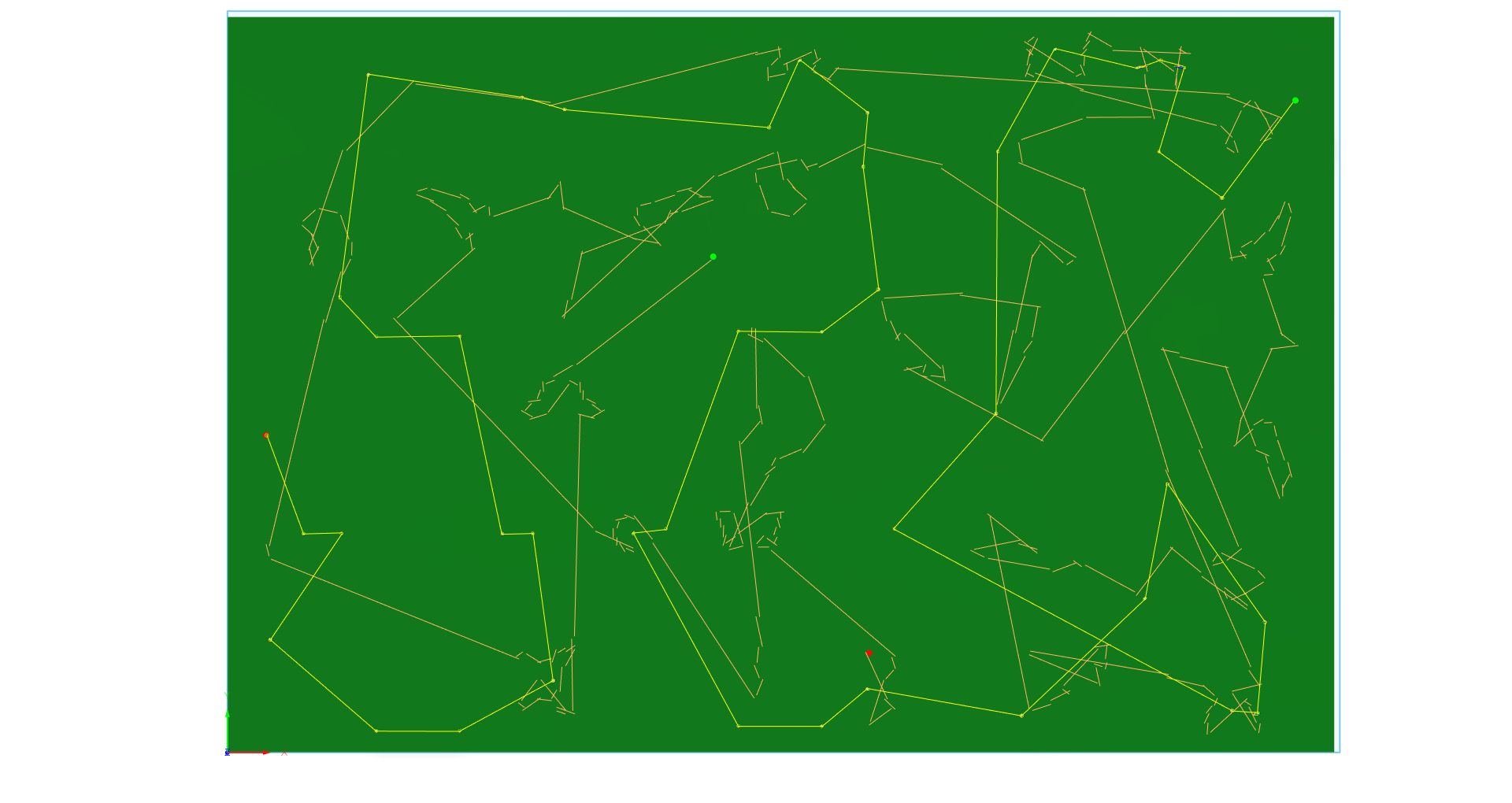
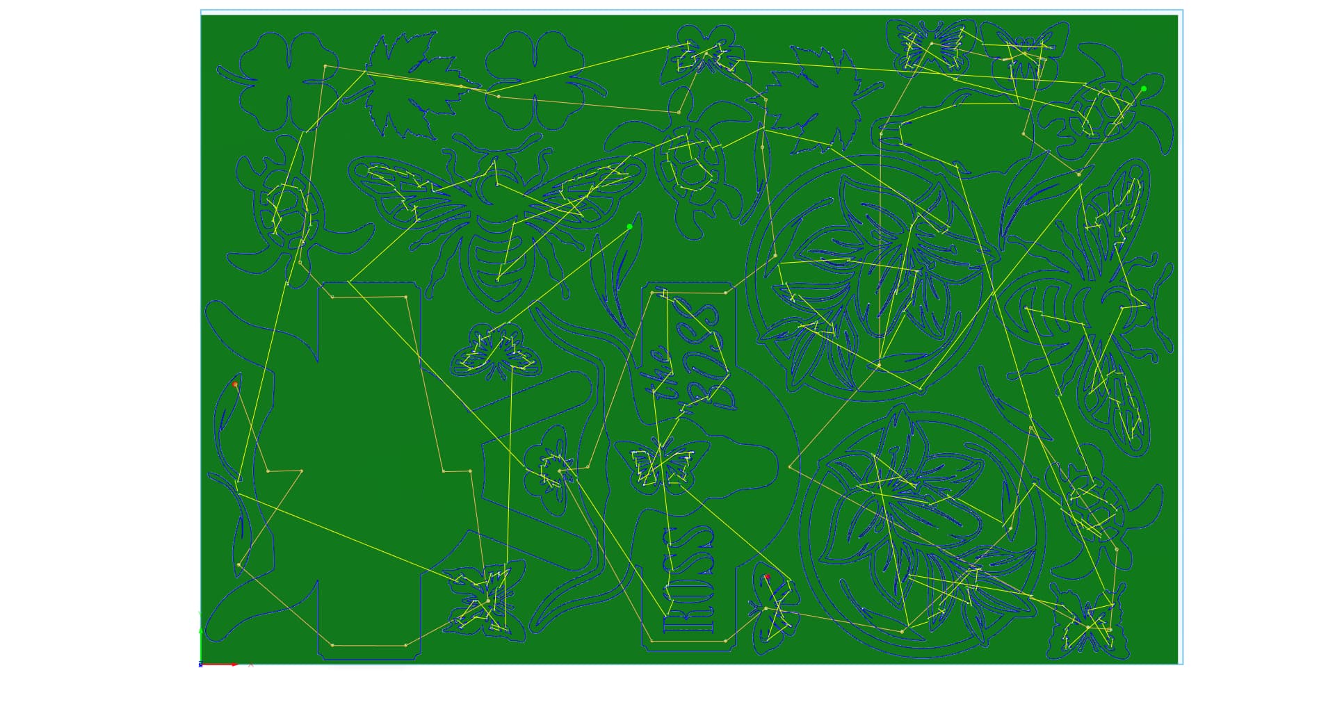
Here is an example. The toolpath and generated for this sheet.


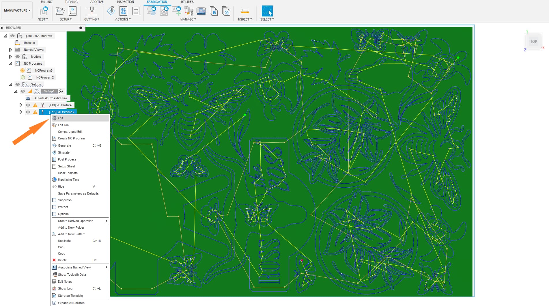
If now I want to make a change to these paths I can right click on the 2D profile (toolpath) I’d like to edit. now I can make my changes in the 2d profile menu and regenerate the toolpath .

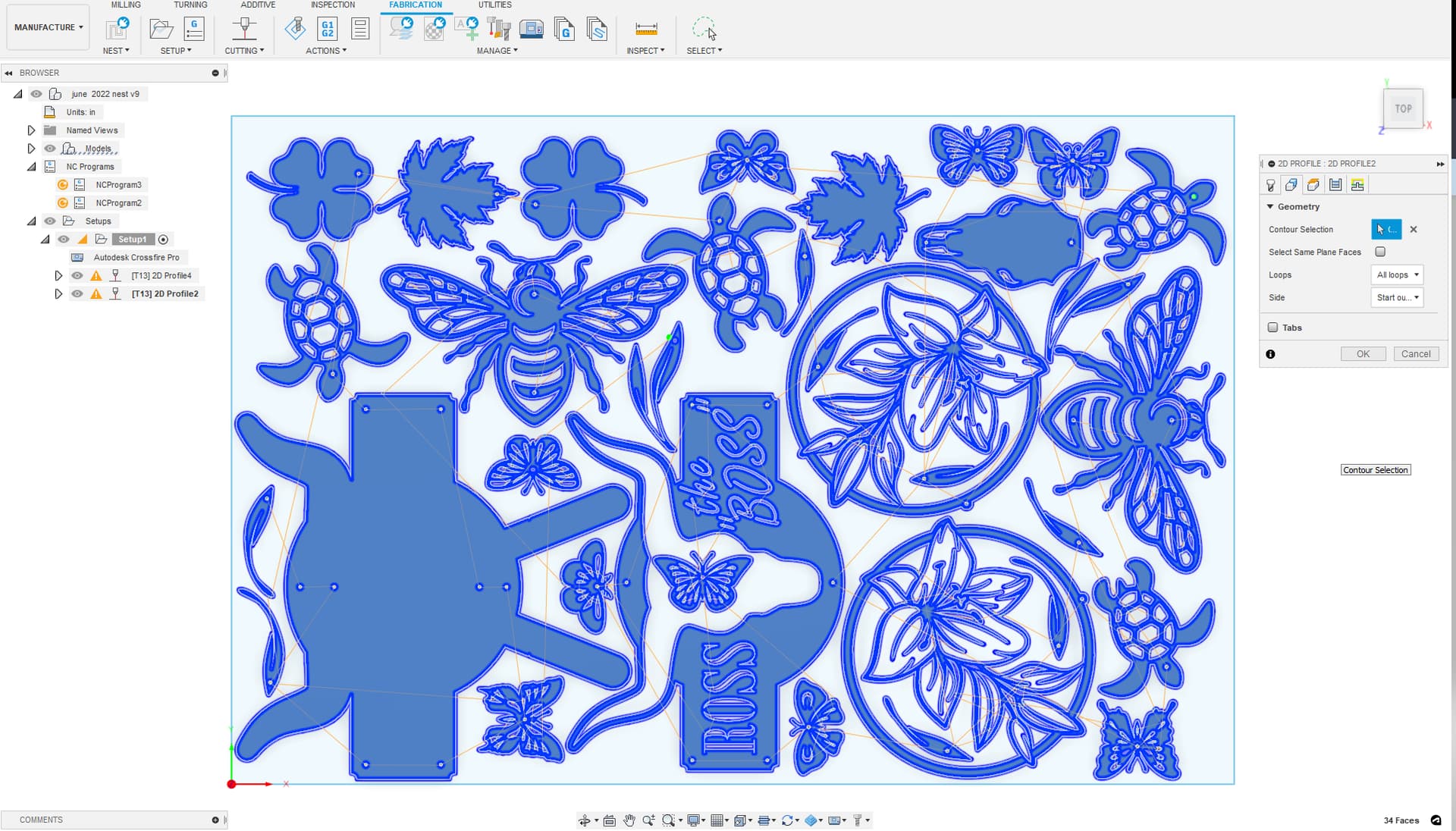
I have two toolpath for this file that when posted will become one g code file

The first 2d profile ( toolpath ) has selected all the hole by selecting the sketch geometry in the 2dprofile>geometry tab. when selecting sketch geometry normally the first selection is correct ( inside out outside red arrow) but if not you can go back and edit it.

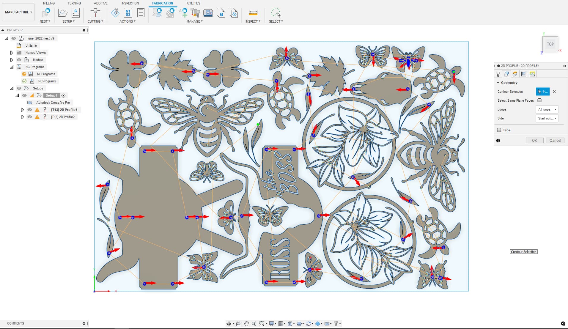
The 2nd 2d profile ( toolpath ) has selected all the body surfaces by selecting the bodies’ faces in the 2dprofile>geometry tab. When dealing with bodies ( extruded sketch geometry) it automatically knows what is inside and outside and applies is accordingly.
]

This link discusses the red arrows inside and outside above and how to spot which one you have

Pierce clearance will also add to your lead in length. What kerf width are you using? If you post your F3D file we can really look into these setting.

Mostly so you do not extinguish your arc when cutting over empty space.

single line cuts are fine. here a example of how to tackle that.

The solution maybe modify your design to accommodate your tool kerf and wanted design outcome. This is likely the kerf width causing this constraint.

The main thing to keep in mind to simplify the toolpath creation process is the extrude your profiles in the design workspace before move to manufacturing. ( you can always go back to extrude the design and return the manufacture space to, F360 is fully parametric)

1 Like

If the tool path fails to link, the software is essentially saying the torch can’t cut it. So if you edit it, isn’t it likely not to work still? Regardless. If I can learn this it will save all the redoing. No more selecting 50 contours and having a few be on the wrong side or whatever and having to start all over. Thank you. So much to learn.

I’ll adjust the original design again. The kerf width is .051. I should get in and measure the problematic areas. If it still fails I’ll post it.

Exactly for whatever combination of inputs and design it calculates that it cannot perform that task.
It might be able to calculate 90% of the other cuts which you still can use.
Just start another toolpath and pick up the remaining contours that were dropped on the first tool path with different parameters for clearance and then you may be able to pick up some of the rest of them.
Normally if I do that I’ll drag the second toolpath to be the first so it’s not trying to cut on already cut out parts.

There is a lot to learn I, put quite a bit of effort into learning fusion 360 and it’s just such a expansive program that’s ever growing.I don’t know if you could ever learn it all.

You’re welcome, post some of your successes or fails on here it would be good to see.

1 Like

I’ll post this because it’s something I’m working on for the table itself, something I plan to share once I have it sorted, built and tested. An alignment bracket that clamps to the table, then gets cut to fit once attached.
I put some purely decorative shapes on the thinnest piece, on the far right. They’re similar to ones I’ve been struggling with. They won’t link in this project. I now know how to edit the tool paths. (thanks!) If I need to redesign the problematic bits, I lose all the tool paths, right? But you’re saying there’s a way to select individual contours and change their parameters, while maintaining the existing tool paths?
Top Guides v4.f3d (435.0 KB)

Looks useful. I think I can see visualize the end product.

Lets start with these decorative triangles on the right.

I start by clicking ang highlighting setup1 in the browser bar. then I start new toolpath by selecting cutting in the above tab. It will add a 2nd toolpath to setup1.

I select these missing contours and develop a toolpath and I’ll used the kerf of .057 from the 1st tool path with no lead in, lead out of pierce clearance.

It misses this little bit of the triangle. why? F360 knows it cant fit .057 in a space that is .04 wide.

now I’ll change the kerf to .04 ( in the toolset )

still does not cut it because fusion does not want the torch to fire over empty space.
Now will try to change the kerf to .039

now it picks up the geometry because it has .001 of material to travel back on.

This is a good example of how fusion 360 deicides to make a path.

you should keep toolpaths that you don’t delete related the sketch geometry when modifying back in the design workspace . You’ll have to reload the out of date toolpath once back in the manufacturing space but most of your work will be saved.

Back at the original sketch I make some modifications


back in manufacturing I have an alert For toolpath out of date on the toolpath ( a orange circle with a rewind arrow)

-Another note is that you can see the phantom image of the outdated toolpath in this shot.

I’ll click right then edit it and hit ok and it will regenerate any geometry that has been changed.

There is a few other things id like to go in to but I’ll have to look at it again tonight.

Here is a little more information on the Red arrows


the red arrows in this shot are on the inside of the soon to be toolpath this mean the toolpath will also end up on the inside. ( this work almost all the time but small and odd shape geometry may sometimes mess with this placement of the arrow so always double check the path after)

you can turn on visibility in the bowser to see the toolpaths that have been generated. (this was and edit so paths had been previously generated.)


now I’ll click all the arrows (besides the K) and they move to the outside of the shape now the paths will generate on the outside

note that when the toolpath cut into the body of the design it appears as grey. this is try to tell you that you are cutting into your finished piece. see the K as the inside cut in white telling you that the cut is made in the off cut of the material.

I’ll be out in the field for the day and will continue on this more tonight.

1 Like

I’ll have to study this quite a bit to understand well enough to use myself. I assume you altered the geometry for teaching purposes?

Should I also assume that while the machine would now attempt those cuts, because they’re tighter than the tool’s actual kerf width, they’ll fail?

It won’t necessarily fail, but it will cut more material away than what you have in the drawing. If you have a .040" line in the drawing and you set the kerf to .039 you can fool Fusion into thinking it can go one direction and then move over .001 and go back the other direction. If your actual kerf is .050, you will get a .050 line going one direction and move over .001 to come back the other direction for a total actual cut width of .051".

In essence it will give the same result as modifying your design to have a .051" width line. In either case, there is always a chance that the cutter will not be happy with only having .001" of metal to maintain the circuit between the work clamp and the torch and it will shut off the torch.

2 Likes

The only geometry I altered is when I went back to the design workspace and rotated the design word upside down, turned the eyeglasses at an angle, move that lower line and an angle. Yes this was for teaching example, to show that the geometry is connected to the tool paths and all you have to do is update (by clicking edit and hitting okay on that toolpath) when you get back to the manufacturing space.
It was a good example to show that the lines and the design workspace are linked to the toolpaths in the manufacturing space.

If the toolpath exists the machine is going try to cut it. the system has no real way of knowing actual how much material the torch is cutting away. So, If you set your kerf width that is too small it’ll over cut your parts by the difference of the real kerf and the kerf set in CAD divided by two.

It’s not that it’ll fail,it’s that it will offset your finished products’ geometry by half the kerf widths difference.

I tried to correct some of my wording up above too.I was in a rush this morning when I was writing things

1 Like