Does anyone know what the actual input amperage is needed for these?
The one manual I happened to find online is blank where is has it.
Ive been having an issue with the plasma going away during cuts on thicker pieces anywhere from 5ipm to 30ipm, and only seems to be a problem when i turn the plazma amperage up.
I put an amp clamp on it and am completely blown away by how much power it is taking, and honestly makes ZERO sense to me unless it is bad.
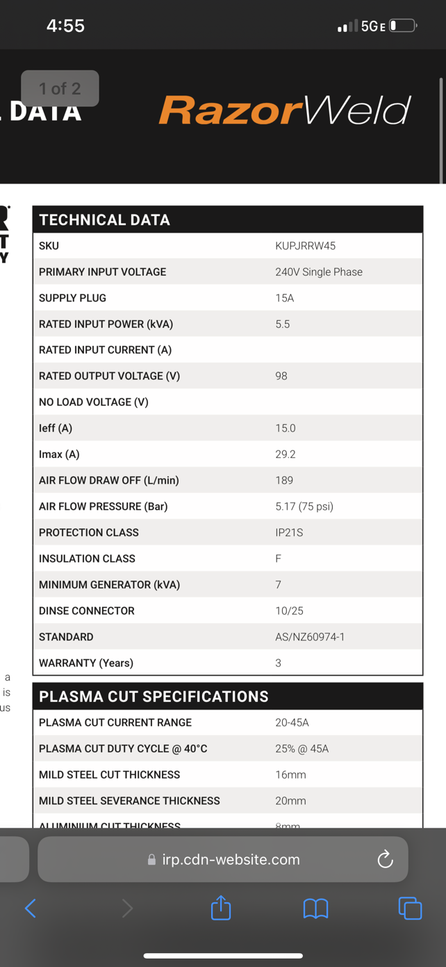
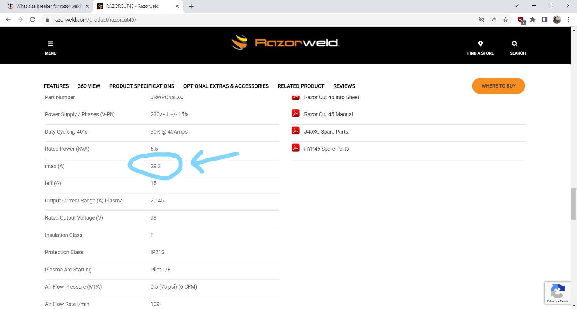
At 28amps, the machine is taking 35amps per 110v leg. That doesnt add up, especially for an inverter. Needing 70amps to output 28amps isnt right. Which makes sense why the torch would turn off.
Originally it was turning off with it set at anything of 25 amps, and an amp clamp of 30 amps per leg, and this was on a 25amp circuit. If i slowly turned up the machine and had an amp clamp reading of anything 30amps or higher it would turn off. (Plasma, not machine or torch output light)
So I changed to a 30amp circuit, and now I can turn it up to around 28-30amps, but anything over 35amps on the clamp it will turn off.
So with that math this thing is going to need at least a 50amp setup, and need 100amps total for a 45amp output???
I hope not, I get maybe 30 seconds of run time, If I turn the machine down to where its at 35amps (on the new outlet) it is fine, but if i exceed 35 amps on this outlet it turns off. My guess is supply voltage is dropping and its turning the torch off.
My miller dynasty tig puts out 280amps and has a 35amp breaker requirement. They are both inverters, so I suspect a problem.
It is measuring live running amperage. At 28amps on the machine, its pulling 34-35amps the whole time.
Max hold on the clamp is not on. Its live measurements. Sits at 0.3 while idling, ramps up to 28ish with pierce and 34-35 while cutting set at 28amps on the plasma.
You may have some kind of resistance in this circuit like a bad connection or wire that’s too small you’re going to have line loss in that circuit your volts will go down and your amps will climb. Especially when that resistance starts to heat up.
Agreed, but its an inverter. They are very efficient compared to transformer style.
The comparison of my tig inverter above at 280 only needs a recommended 35amp outlet.
Even at 1:1 it would need a 45amp circuit. The math is going to work out to around a 60-70 from only 45amps with how it is now
Its 8ga, about 10ft long from the breaker box, but on a 35amp breaker. Having a hard time finding a 50+ breaker that isn’t $1k on this old panel.
I agree completely on resistance. The original outlet it was on, the only reason why I went off into this direction of testing is because the wire was warm on the 25amp circuit. That circuit is 12 or 14ga on a 25amp breaker.
I see what you’re saying if you turn up the voltage more on your machine you extrapolate that you’ll be running 70 amps input while running 45 amp output on the machine
Yes roughly .5 amps difference.
I just got off the phone with razor weld and the agreed it’s not right, however they still didn’t give a firm answer of how big the breaker should be. He just kept saying it on a 45amp machine he doesn’t see it needing more than 25-30amp breaker. And mentioned it should be around half in to out amperage ratio.
He suspects the board being bad. Joy, literally 20 minutes of run time and “passed” their QC test.