I have a problem that I never really noticed before but I have not needed this level of precision. I am marking two holes for later cutting on the mill. I am using easyscribe to mark those holes or crosses where the holes go. These holes need to mate up with some existing holes in plate steel. When I did the cad drawing, I printed it 1-1 scale and the holes and cross hatch line up with the existing holes perfectly. I put the DXF file in sheetcam and created the tap file for the crossfire pro.
The scribe marks worked well but the hole spacing in the x axis is off. The holes are spread apart about 2.mm or .093" too far. the spacing in the Y axis is right on. I am wondering if the settings for the x axis rotation might be off a little in the post processor or where ever that would be. I have not really noticed this in the past but this is the first time I have used the scribe tool and it is so much more accurate than a plasma hole that this problem now shows up. Anyone had this issue and have any ideas?
The spacing is off by 2 mm but how far are the holes apart? It would also be good to do a test scribe square to see if you are getting a parallelogram, rhomboid or some other odd shape.
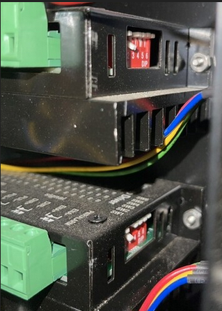
If is really rare but sometimes the stepping levers get flipped on the drivers. You would need to open up the enclosure. Here is how the switches should be set (everything up except the second one):
 .
.
Check your voltage out of the power supper (should be 36 volts):
Adjusting power supply voltage.pdf (2.4 MB)
Depending how much you use it, most of us clean and lubricate the lead screws nearly every time. WD-40 is fine.
I will check that out. The spacing is 60mm or 2.38 inches. The axis are lubed and not many hours. I will check the switches and look into testing voltage.