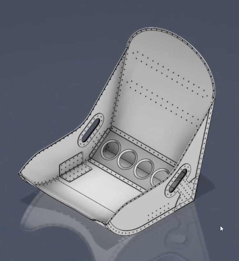
I’ve been working on these seats for…a while. Hours and hours and HOURS into their design, and I’d like to ultimately manufacture them, which is a large part of the reason I purchased a Langmuir Table.
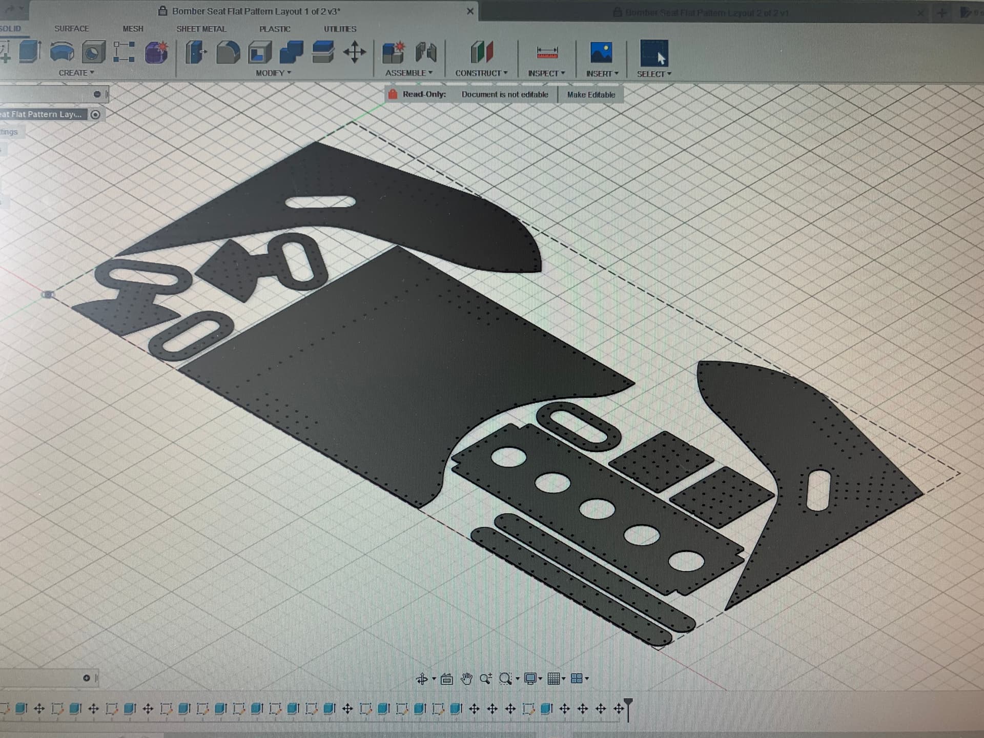
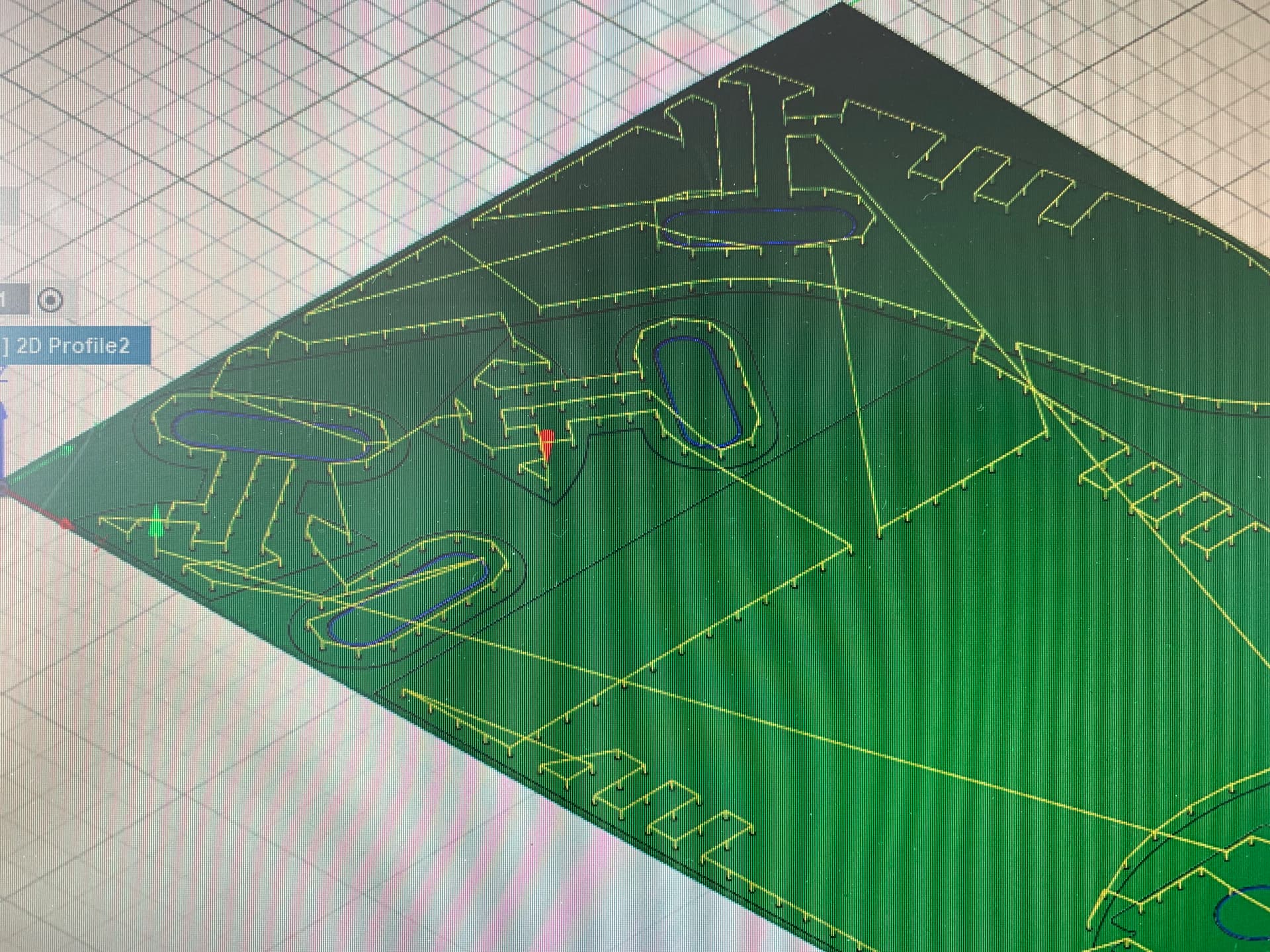
I’ve got the flat panels all nested to fit inside of my aluminum sheet in Fusion and when I go into the manufacturing space, I’ve created a tool with a kerf a thousandth smaller than the 100’s of holes in my design, as I’ve seen a few threads on here that say this will allow me to generate a tool path to “peck” (pierce on a low amperage) the center of the hole.
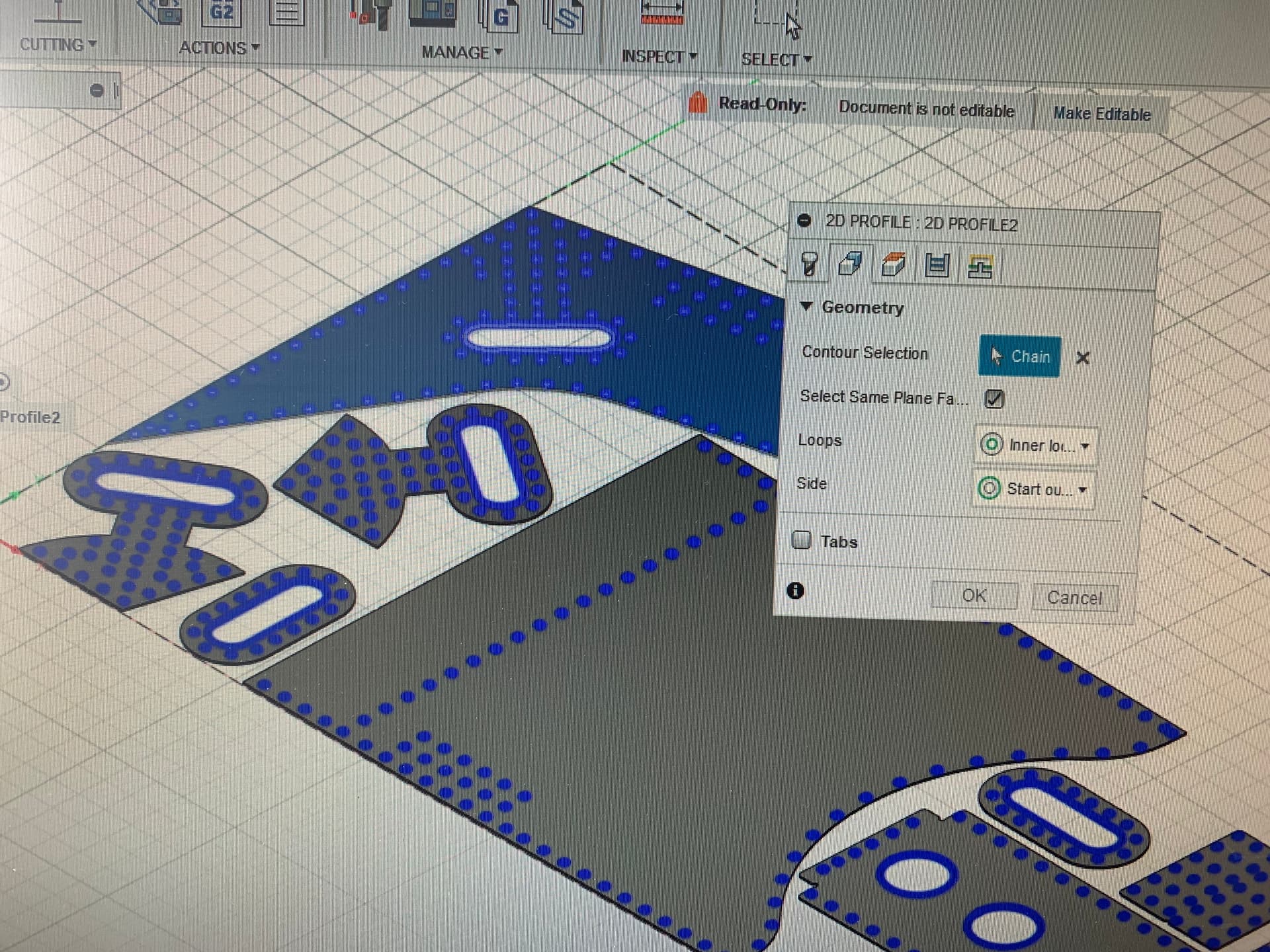
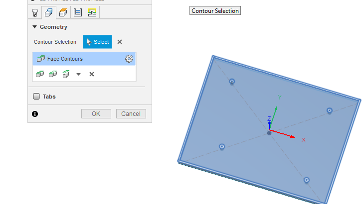
The problem is, the only way that a toolpath to peck the hole centers will generate is if I select the full face, and a geometry setting of inner loops, but this also selects my other inner geometry, which wouldn’t cut correctly with Fusion thinking I have a 0.128” kerf width. I can’t seem to eliminate the other “inner loops” after bulk selecting the faces…
And I’m not being lazy; I’ve tried to go in and just select the holes, and the machine thinks the outside detail doesn’t matter and cuts around the outside of the hole regardless of the other selections I make.
And if I manually select the holes and the outside geometry independent of the inner detail, it always defaults to cutting the outside geometry FIRST no matter what other choices I make (including preserve order). It’s like a glitch, or something, but I’m making myself crazy trying to trick Fusion into doing what I want…
The only option that I think I’ve found is if I go through the G-code line by line and put parenthesis around the torch firing commands on the lines that represent the inner features, but I’m not confident enough with G-code that I’ve caught it all, and the aluminum is too expensive to make a mistake…
I hope I have explained this well enough to make sense to anyone trying to help me. I apologize I have not. I’m sure this would be much easier in sheetcam but I’m out of money.
This might be an instance where I am just too unfamiliar with the software. I figured I would have to do a second NC program with the second toolpath. Is there a way to do two toolpaths in the same NC program (in Fusion)?
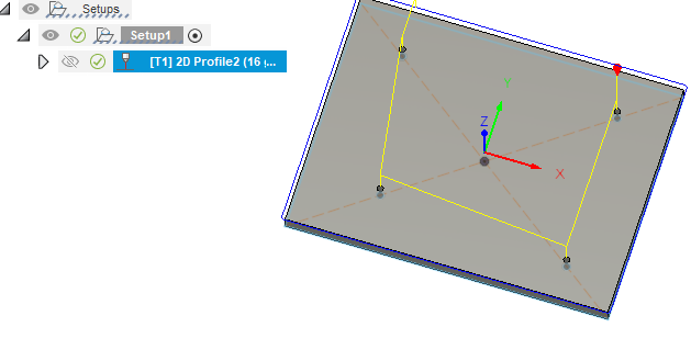
Ok, I figured it out. I had to click the arrows after I click the holes to change the operation from inside to outside.
Alright, so the two path thing is going to work great.
My only other question is whether there is a way to bull select the holes without selection the other inside geometry? This one isn’t crucial, because I can select all the holes fast enough…there’s just quite a few.
That would be better for sure, but I wanted to draw the part to scale when I designed it, and I couldn’t really wrap my brain around an easy way to do what you’re saying. Depending upon how this goes, I may ultimately have these laser cut, in which I think a 0.129” hole could be possibly be cut to spec. Or maybe that’s just wishful thinking…
I decided to investigate this further. I started with the assumption that Fusion CAM would try nearly any contour that allowed the kerf width of your tool. In this case my tool was for 16 gauge steel and it was set at 0.045 inches.
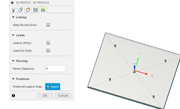
I just made a basic shape and put four holes: three were sized 0.045 inches and one was 0.05 inches. I extruded the part. I picked the contours by picking the body and removed lead-ins, lead-outs and pierce clearance. The result: it only picked the 0.05 inch hole. By process of elimination, as @TinWhisperer suggested, a micro addition is needed. I changed all holes to 0.046 inches and it worked!!!
So far it is just a theory as the simulation worked. I have 95% confidence that it will make a suitable pierce based on other successes with small areas. It will be a touch on the ugly side but it is primarily used to mark the center of a hole that you plan to drill with a drill bit. That will remove the dross and the hole should be centered where you need it.
Edit: If I were to do this with a real project, I would “project” the holes onto another sketch. That way, I could pick all the other contours with more traditional lead-ins, lead-outs and for the “pecks” on a separate tool path, there would be no lead-ins, lead-outs, pierce clearances. The beauty of this method is that you don’t have to select each individual peck mark.
Thanks for the quick response. I am interested in pecking for reasons you mentioned, and I am also interested in “pecking” to mark the location of the bend line (marked by two peck holes) for a brake when I use sheet metal tools in fusion.
It’s actually pretty ugly, David. At least it was with my Primeweld Cut 60. That machine had an issue with pierce delays set below half a second, and at half a second the actual delay was somewhat inconsistent, and the blow back pressure was all over the board. On my 0.060” aluminum bomber seat project it was a 50/50 deal whether I’d get a “peck” or a full pierce, and the holes were out of alignment by as much as 1/8”. I’m thinking the latter issue has to do with the arc wandering, possibly due to a lag in the air solenoid opening…I’m not really sure.
My new Everlast 62i will delay all the way down to 0.1 second (seemingly reliably), so I will have to attempt this again at some point…
Aluminum is simply terrible with the specks of aluminum that gets flicked around. After I had cut some aluminum, I then cut some 12 gauge steel. There were parts of the steel that cut perfectly and intermittantly did not cut all the way through.
I took the torch apart and found four little pieces of aluminum that were rattling around in there. And I was not doing any small areas. I didn’t even know how to do small things back then.