Hi, just last night I was able to cut my first part on my CF Pro table. Very excited!
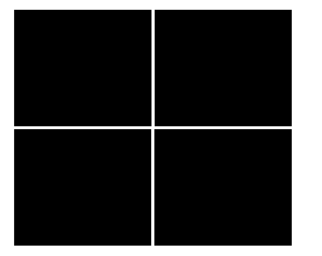
I was curious what is the right way to go about nesting squares so that the in-between plasma route cuts the sides of two adjacent squares at the same time.
Motivation here is to reduce the number of piecing events and overall plasma burn duration. In the sketch below the white cross in between plates would be the common path. Do I design for this common path width in CAD via kerf compensation or the correct way to do this is via CAM like Fusion 360?
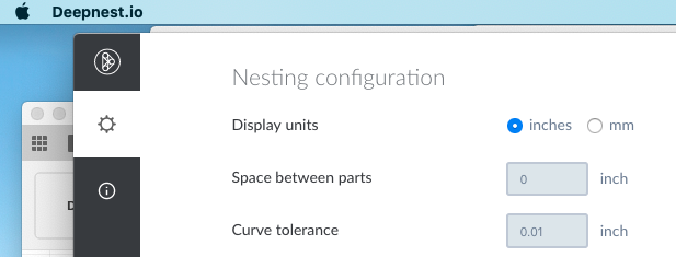
No, to enable common line cutting you have to set the distance between parts at 0. So your drawing will have to account for that kerf width loss, if it’s big enough to matter for your part, because by merging the common lines you’re taking away the ability to compensate for the kerf by the CAM program.
In Deepnest I will leave the margin as 0, but in the CAD drawing I will enlarge each rectangle by kerf width, because during cutting each rectangle will loose 0.5*kerf from each side.
Actually, you could avoid that problem by just doing no offset in CAM. It would then cut the outer contours the same as the inner. So you could compensate for everything.
You could make 2 different cut profiles select all the horizontal lines in one and all the vertical lines in the other but not sure how that would work out either.
I only use sheetcam for the odd sign or something similar that I make so I’m not 100% on what kind of cutpath it will generate.
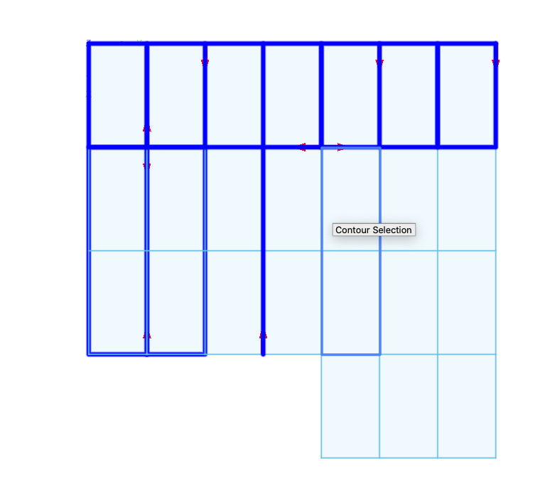
Yes @Fortifyfabworks, but when I click on path the Fusion360 CAM selects the complete paths and sometimes just the lines. I am not aware how to select strictly vertical or horizontal lines.
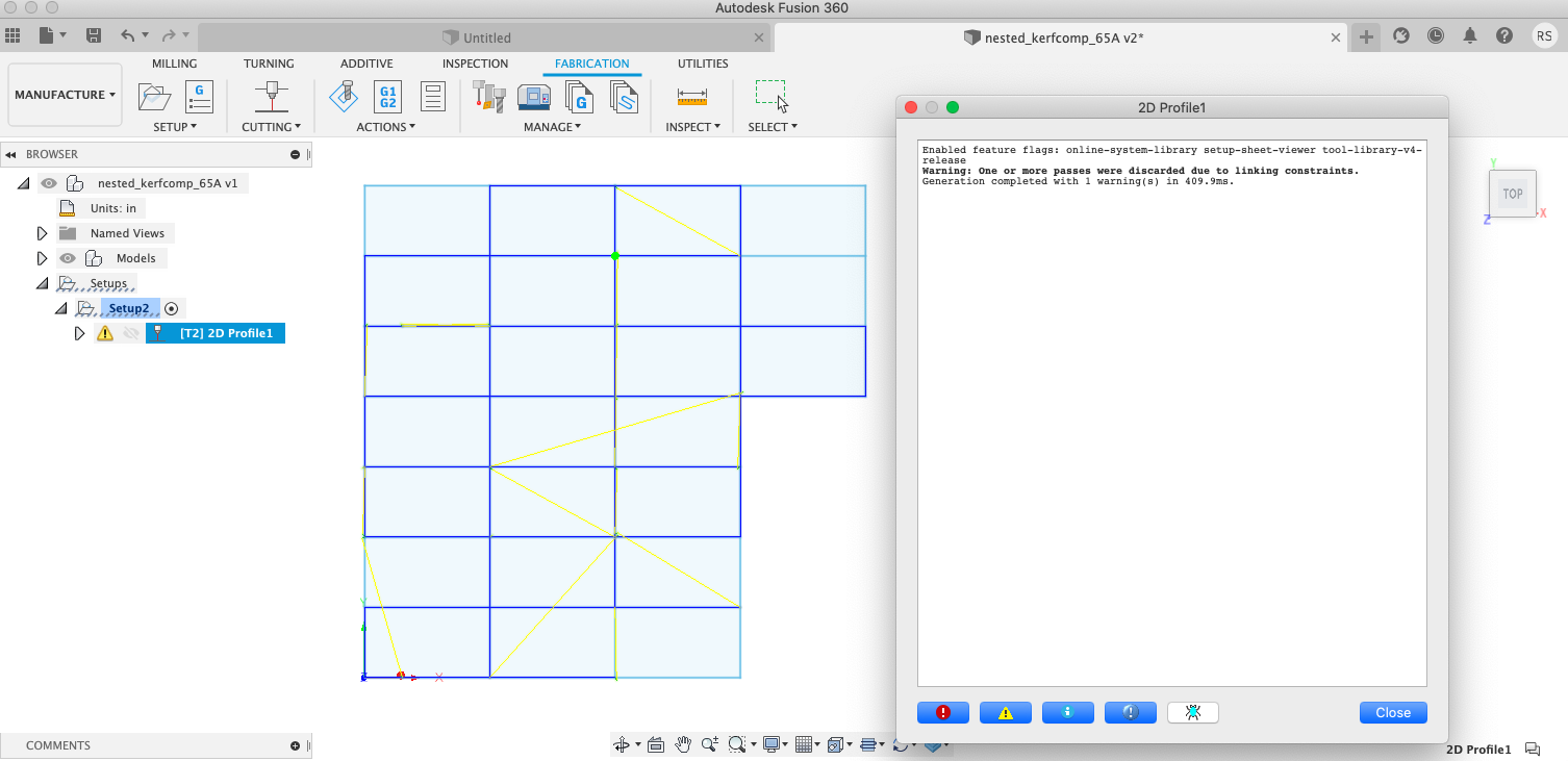
Is it possible that issue is caused by this warning that I get?
I really don’t think you’re going to have any success with this.
I can appreciate trying to save metal I know its expensive but if you space your parts double your kerf width your not wasting any steel.
What plasma cutter do you have?
About your consumables I cut 1000’s of inches every week and 1000’s of pierces and I’ll go through a set of consumables that cost me $12.
In my opinion your spending a lot of time for no gain and possible miscut parts if they need to be a certain size.
About your consumables I cut 1000’s of inches every week and 1000’s of pierces and I’ll go through a set of consumables that cost me $12.
Thank you for providing this data point. It is hard for me to disagree with you as I wasted pretty much the whole day today and we don’t even cut 100 inches per day.
Lol yeah, there’s an equation here to figure out how much troubleshooting is worth it.
Deep nest seems to export the new file with multiple segments that will just depend on how their machine learning did it. With what you were trying to do with uniform rectangles, it would have been easier to just design the file using common lines in the first place, and then you would have the paths how you want them and could select horizontal and vertical in CAM. only thing I’m not sure on is if it would let you run one path over another. Plus you’d have to account for the material moving once it loses a support side possibly.
There’s a lot to consider, more than I would have though. Lol
Going through all this with you had now made me not very eager to use common line nesting.
Trial and error is how things happen. Trust me I know all about wasting time trying to build something or improve something and at the end of the day something clicks in my head on a better way to do it and off to the scrap bin that day goes.
With the 85 you shouldn’t have any issue cutting anything you want or the table can handle at least.
What if you had two layers with one over the top of the other exactly… Only horiz lines on one, and verts on the other…? I suppose a third layer with the outline as well…